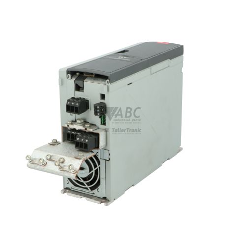
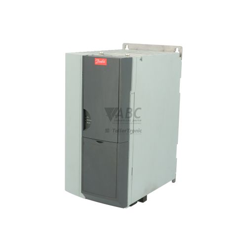
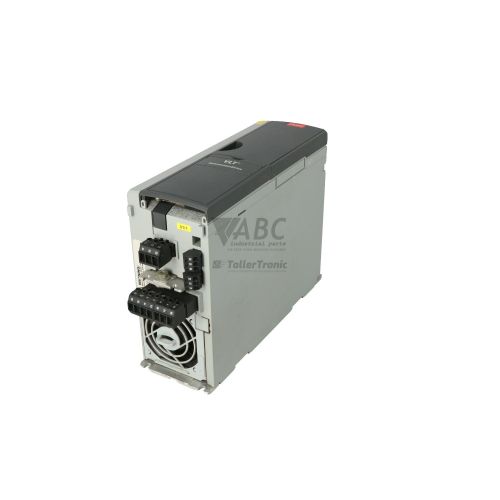
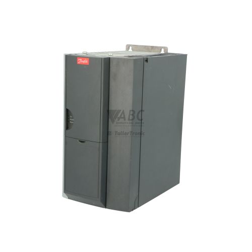
Danfoss 131B0026 FC-302PK37T5E20H1XXXXXXSXXXXAXBXCXXXXDX VLT AutomationDrive FC 302 VFD


Het item werd toegevoegd aan uw offerteaanvraag
Product Information
The Danfoss 131B0026 is a 0.37 kW (0.5 HP) variable frequency drive from the VLT AutomationDrive FC 302 series, designated under type code FC-302PK37T5E20H1XXXXXXSXXXXAXBXCXXXXDX. Operating on a three-phase mains supply voltage from 380 V AC to 500 V AC, this compact frequency converter delivers 1.3 A continuous output current at 380–440 V and 1.1 A at 460–500 V with an output frequency range of 0 to 590 Hz. Housed in an IP20 chassis enclosure with an integrated Class A1/B RFI filter, it features advanced control algorithms including Voltage Vector Control (VVC+), Flux Vector Control, and permanent magnet motor control, along with built-in Safe Torque Off (STO SIL 2 / PL d) functional safety.
For system integration, the drive provides 6 digital inputs, 2 digital outputs, 2 analog inputs, 1 analog output, 2 relay outputs, an onboard RS-485 serial port supporting Modbus RTU and Danfoss FC protocol, and a USB 1.1 Type B service interface. Replacing a unit in production requires transfer of the device parameter profile and any option cards, such as MCA 120 PROFINET, MCA 101 PROFIBUS DP, MCA 121 EtherNet/IP, or MCA 124 EtherCAT fieldbus modules. Parameter cloning can be completed using the LCP 102 graphical local control panel or the Danfoss VLT Motion Control Tool MCT 10 software to restore operational settings, motor data, and I/O scaling prior to restarting the system. ABC Industrial Parts can support maintenance teams requiring tested spare drives to minimize system downtime.
Diagnostic monitoring is provided directly on the front panel status LEDs—a green On LED indicating control power, a yellow Warn LED indicating active non-tripping warnings, and a red Alarm LED indicating a tripped condition. Detailed fault text is visible on the optional LCP 102 display, stored in parameter group 15-4* Drive Log, or accessible via MCT 10 software. Real-time operating currents, voltages, and thermal states can be checked in parameter group 16-**. Common trip conditions include Alarm 7 DC overvoltage, Alarm 13 overcurrent, and Alarm 14 earth fault, which require verifying external supply lines, motor insulation, and deceleration ramps. Internal hardware failures, such as Alarm 38, cannot be serviced in the field and require unit repair or replacement through ABC Industrial Parts.
Technical Specifications
| Manufacturer | Danfoss |
| Part Number | 131B0026 |
| Model / Type Code | FC-302PK37T5E20H1XXXXXXSXXXXAXBXCXXXXDX |
| Product Family | VLT® AutomationDrive FC 302 |
| Component Type | Variable Frequency Drive |
| Rated Power | 0.37 kW |
| Rated Power | 0.5 HP |
| Supply Voltage Range | 380 - 500 V AC (3-Phase) |
| Continuous Output Current (380-440V) | 1.3 A |
| Continuous Output Current (460-500V) | 1.1 A |
| Output Frequency Range | 0 - 590 Hz |
| Digital Inputs | 6 |
| Digital Outputs | 2 |
| Analog Inputs | 2 |
| Analog Outputs | 1 |
| Relay Outputs | 2 |
| Enclosure Rating | IP20 / Chassis |
| Onboard Serial Interface | RS-485 (Modbus RTU / FC Protocol) |
| Service Interface | USB 1.1 Type B |
| Control Algorithms | VVC+, Flux Vector Control, Permanent Magnet Motor Control |
| Integrated RFI Filter | Class A1/B |
| Functional Safety | Safe Torque Off (STO) SIL 2 / PL d |
Programming and Configuration
Parameterization and setup for the Danfoss 131B0026 FC 302 drive are executed using the Danfoss VLT Motion Control Tool MCT 10 software or local control panels, including the graphical LCP 102 and numerical LCP 101. The MCT 10 software connects via the onboard USB 1.1 Type B service port or RS-485 network, permitting online configuration, offline parameter project creation, and real-time monitoring of drive parameters.
Motor setup parameters in group 1-2* must be configured to match the attached motor nameplate details when commissioning a replacement. Drive parameter backups can be stored on the LCP 102 panel memory or exported via MCT 10 for rapid cloning across multiple units. If a parameter reset occurs, reflected by Alarm 80, the drive defaults to factory settings and must be fully re-parameterized or restored from a known backup file before returning to service.
Communication and System Integration
Network integration is supported natively through an onboard RS-485 interface supporting both Modbus RTU and Danfoss FC protocol. This allows multi-drop network connections for command control, reference speed tracking, and status monitoring directly from a host controller or PLC without requiring additional option cards.
For high-speed industrial network communication, the modular architecture includes option slots accepting plug-in fieldbus interface cards. Supported communication options include MCA 120 PROFINET, MCA 101 PROFIBUS DP, MCA 121 EtherNet/IP, and MCA 124 EtherCAT. When replacing a drive equipped with an option card, the fieldbus interface card must be transferred or installed into the spare drive to maintain network node address settings and communication mapping.
Diagnostics and Status Indication
Diagnostic monitoring on the Danfoss 131B0026 drive combines visual LED indicators, parameter readouts, and event history logs. Parameter group 16-** provides real-time system monitoring for line voltages, output current, thermal load percentage, and I/O logic states. Parameter group 15-4* logs past trip events and alarm details for retrospective fault diagnosis.
Visual indication is provided by three front-panel status LEDs. The green On LED confirms control card power, the yellow Warn LED alerts operators to warning conditions while allowing continued drive operation, and the red Alarm LED indicates an active drive trip state where output power to the motor is disabled.
Status LED Indicators
| LED | Color/Status | Meaning |
|---|---|---|
| On (Green) | Green - Solid | Control card is powered up and operating properly. |
| Warn. (Yellow) | Yellow - Solid / Flashing | A warning condition is active (drive continues operating). |
| Alarm (Red) | Red - Solid / Flashing | An alarm state has tripped the drive (drive is stopped or coasted). |
Replacement and Spare Part Considerations
When replacing a Danfoss 131B0026 drive (type code FC-302PK37T5E20H1XXXXXXSXXXXAXBXCXXXXDX), ensure the replacement unit matches the required power rating of 0.37 kW (0.5 HP) and input voltage specification of 380–500 V AC. Verify that any installed fieldbus option cards—such as MCA 120, MCA 101, MCA 121, or MCA 124—are physically moved to the replacement drive's option slots.
Spare drives received in factory-default state must be configured with original parameter values prior to operation. Use the LCP 102 graphical control panel or MCT 10 software to download the parameter backup file. Particular attention should be paid to motor data in parameter group 1-2*, analog signal scaling on terminals 53 and 54, and Safe Torque Off (STO) wiring to ensure safe and correct machine operation.
Error Codes & Fault Codes
The following error codes may be displayed during operation or diagnostics:
| Code | Name | Description | Possible Cause | Recommended Action |
|---|---|---|---|---|
| Alarm 2 | Live zero error | Signal on Terminal 53 or 54 is less than 50% of preset value set in parameter 6-10, 6-12, 6-20, or 6-22. | Broken wire, disconnected signal source, or incorrect parameter scaling. | Check analogue signal connection and wiring. Verify signal level and parameter settings. |
| Alarm 4 | Mains phase loss | A phase is missing on the supply side, or mains voltage imbalance is too high. | Blown supply fuse, loose line wire, or severe mains line drop. | Check line supply voltages and input fuses. |
| Alarm 7 | DC overvoltage | DC bus voltage exceeds limit (approx. 800 V DC for T5 drives). | Motor regenerating back into drive due to short ramp-down time, or high mains voltage spike. | Extend deceleration time, connect brake resistor, or check supply voltage. |
| Alarm 8 | DC undervoltage | DC bus voltage drops below low-voltage threshold (approx. 373 V DC). | Mains voltage drop, temporary power loss, blown fuse. | Check line supply voltage and input connection. |
| Alarm 9 | Inverter overloaded | Inverter thermal memory protection reached 100% overload limit. | Extended operation over 100% rated current, mechanical binding in load. | Reduce load on motor, check mechanical driven equipment. |
| Alarm 10 | Motor ETR overtemperature | Electronic Thermal Relay (ETR) calculated motor temperature exceeds threshold. | Motor overload, operation at low speed without external cooling fan. | Check motor load and forced-cooling requirement. |
| Alarm 13 | Overcurrent | Inverter peak current limit is exceeded. | Short circuit on motor cables, ground fault, sudden shock load, or incorrect motor parameters. | Check motor and wiring insulation. Verify motor data in parameter group 1-2*. |
| Alarm 14 | Earth fault | Current leakage from output phases to ground exceeds trip limit. | Ground fault in motor lead, motor winding ground fault, excessive cable length. | Check motor leads and motor winding insulation resistance using a megohmmeter. |
| Alarm 16 | Short circuit | Short circuit across output terminals U, V, W. | Short circuit in motor windings or output cables. | Check motor windings and connection cables for short circuits between phases. |
| Alarm 29 | Power card overtemperature | Heat sink temperature sensor exceeded safety limit. | Clogged heat sink, cooling fan failure, ambient temperature too high. | Clean heat sink fins, check cooling fan operation, ensure adequate ventilation. |
| Alarm 30 | Motor phase U missing | Phase U connection between drive and motor is missing. | Broken motor cable conductor, loose terminal connection. | Check motor connection on terminal U/96. |
| Alarm 31 | Motor phase V missing | Phase V connection between drive and motor is missing. | Broken motor cable conductor, loose terminal connection. | Check motor connection on terminal V/97. |
| Alarm 32 | Motor phase W missing | Phase W connection between drive and motor is missing. | Broken motor cable conductor, loose terminal connection. | Check motor connection on terminal W/98. |
| Alarm 38 | Internal fault | Internal hardware failure on control card or power card. | Hardware component failure, damaged micro-controller or power card communication. | Internal hardware fault — power cycle drive; if fault persists, return unit for repair or service. |
| Alarm 47 | Control card 24 V supply low | 24 V DC supply on control card is below minimum operating threshold. | External 24 V load on control terminals overloaded or short-circuited. | Disconnect external 24 V wiring from control terminals and re-test. |
| Alarm 80 | Drive initialized to default | Drive parameter settings have been reset to factory default values. | Manual initialization procedure executed or memory corrupted. | Re-parameterize drive or restore parameter backup file using MCT 10 or LCP 102. |
Frequently Asked Questions
How do I back up and restore parameters on the Danfoss 131B0026 FC 302 drive?
Parameter settings can be backed up and restored using the optional Danfoss LCP 102 graphical local control panel or through a PC connection using Danfoss VLT Motion Control Tool MCT 10 software via the onboard USB Type B port or RS-485 interface.
What fieldbus communication options are supported on this FC 302 drive?
The drive features built-in RS-485 serial communication supporting Modbus RTU and Danfoss FC protocol. It can also be fitted with optional fieldbus cards including MCA 120 (PROFINET), MCA 101 (PROFIBUS DP), MCA 121 (EtherNet/IP), and MCA 124 (EtherCAT).
What causes Alarm 7 (DC overvoltage) on the Danfoss 131B0026 VFD?
Alarm 7 occurs when the DC bus voltage exceeds approximately 800 V DC. This is typically caused by motor regeneration during fast deceleration, high line supply voltage spikes, or an improperly sized deceleration ramp. Resolving it involves extending deceleration time, checking supply voltage, or installing a brake resistor.
How is functional safety implemented on the Danfoss 131B0026 drive?
Safe Torque Off (STO) is integrated directly into the drive, compliant with ISO 13849-1 PL d and IEC 61508 SIL 2 standards. It prevents the drive from generating torque at the motor shaft without requiring external safety contactors.
What should I do if the drive displays Alarm 38 (Internal fault)?
Alarm 38 indicates an internal hardware failure on the control card or power card. First, power cycle the drive. If the fault persists upon power-up, the unit has an internal hardware defect and requires repair or replacement.
Take advantage of our exchange formula
A defective product does not have to be worthless. At ABC Industrial Parts, you can hand in defective products and immediately benefit from a discount on your new purchase. This is a smart way to save money while contributing to a circular economy.
Play it safe with our warranty conditions
Industrial plants prefer to keep running invariably, no matter what. Therefore, it is essential that you can rely on high-quality products and/or sustainable repairs. With our warranty conditions, you can count on certainty, whether you choose new, used or repaired products.
Data backup and recovery
Have you lost valuable parameters or data due to a malfunction while the manufacturer no longer provides support? At ABC Industrial Parts, we help you secure this data, both for common and specific products.
Specific firmware and hardware versions
If you are working with specific hardware or firmware versions that are no longer available from the manufacturer, ABC Industrial Parts is your partner. When making your enquiry, clearly state which versions you need, we will then look at the possibilities of supplying those versions, so that your installations continue to function optimally.
Disclaimer:
We are not an authorised distributor of Danfoss.
Product photos are for illustration purposes only and may differ from the actual product delivered.
Some of the content on this page was created with the help of AI. While we strive to provide accurate and up-to-date information, errors may occur.