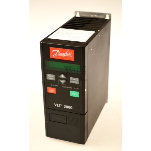
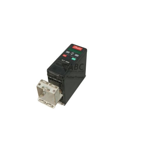
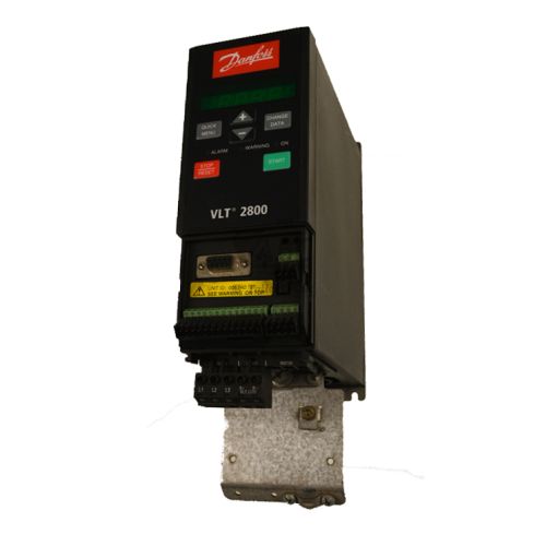
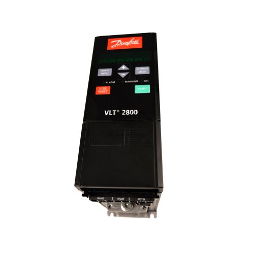
Danfoss 195N1063 VLT2830PT4B20STR1DBF00A00 – VLT 2800 Frequency Inverter 3kW 4HP


Het item werd toegevoegd aan uw offerteaanvraag
Product Information
The Danfoss 195N1063 (model designation VLT2830PT4B20STR1DBF00A00) is a 3-phase AC frequency inverter from the VLT 2800 series designed for precise motor velocity and torque regulation. Operating with a 380 to 480 V AC supply, this 3.0 kW (4.0 HP) drive delivers a continuous output current of 7.2 A and an intermittent rating of 11.5 A across an output frequency range of 0 to 1000 Hz. Built in a compact IP20 rated B20 frame footprint that enables side-by-side panel mounting, the inverter incorporates Voltage Vector Control (VVC+) and user-selectable V/f motor control modes. The unit also features an integrated dynamic brake chopper for regenerative deceleration management and a built-in Class A1 RFI filter for electromagnetic compliance in industrial environments such as material handling conveyors, pumps, fans, and packaging equipment.
Control and system integration are supported through five programmable digital inputs, two analog inputs, one analog output, and one programmable relay output, along with an integrated RS-485 serial communication port supporting Modbus RTU and Danfoss FC Protocol up to 38,400 bit/s. When replacing an existing unit, setting up a spare drive requires matching physical wiring, control terminal assignments, and transferring drive parameters. Drive settings are stored in internal non-volatile EEPROM memory capable of holding up to four independent parameter setups. Initial setup is simplified using Automatic Motor Adaptation (AMA), which measures stator resistance and inductance at motor standstill without shaft rotation. Parameter backup and restoration can be executed via the Local Control Panel (LCP) keypad or through Danfoss MCT 10 setup software, where ABC Industrial Parts can assist maintenance teams with parameter extraction or donor unit configuration setup.
Operational monitoring and diagnostics are provided via the Local Control Panel display, internal fault logs (parameters 615-617), and three status LEDs: a yellow WARNING light, a red ALARM indicator for trip conditions, and a green BUS LED showing RS-485 serial communication activity. When errors occur, detailed numeric fault codes—such as earth faults, overcurrent, or voltage warnings—are stored in the diagnostic buffer and viewable via the LCP or MCT 10 software. Initial troubleshooting should verify line supply voltages, input fuses, control signal levels, and motor insulation resistance. When internal electronics or power driver board failures occur, such as switch-mode power supply or EEPROM faults, internal hardware repairs are not field-serviceable, making unit replacement or technical repair through ABC Industrial Parts the standard route back to active operation.
Technical Specifications
| Manufacturer | Danfoss |
| Part Number | 195N1063 |
| Model / Type Designation | VLT2830PT4B20STR1DBF00A00 |
| Product Family | VLT 2800 |
| Component Type | Frequency Inverter |
| Rated Power | 3 kW |
| Rated Power (HP) | 4 HP |
| Supply Voltage Range | 380 - 480 V AC |
| Continuous Output Current | 7.2 A |
| Intermittent Output Current | 11.5 A |
| Output Frequency Range | 0 - 1000 Hz |
| Control Method | VVC+ / V/f |
| Digital Inputs | 5 |
| Analog Inputs | 2 |
| Analog Outputs | 1 |
| Relay Outputs | 1 |
| Enclosure Protection Rating | IP20 |
| Integrated Serial Interface | RS-485 |
| Supported Fieldbus Protocols | Modbus RTU, FC Protocol |
Programming and Configuration
The Danfoss 195N1063 frequency inverter utilizes non-volatile internal EEPROM memory to store system parameters, retaining up to four independent parameter setups. Drive configuration can be managed directly at the machine using the optional Local Control Panel (LCP) or remotely over RS-485 serial communication.
Commissioning is streamlined through the Automatic Motor Adaptation (AMA) function. Executed at motor standstill without applying rotation, AMA measures stator resistance and inductance to optimize motor control characteristics under Voltage Vector Control (VVC+) or V/f operation. Parameter backup, restoration, and offline setup are supported via Danfoss MCT 10 setup software.
Communication and System Integration
The drive includes an integrated RS-485 serial communication interface supporting Danfoss FC Protocol and standard Modbus RTU fieldbus networks at transmission speeds up to 38,400 bit/s. This allows direct connection to higher-level controllers and supervisory control systems for automated speed reference and status monitoring.
Physical control and feedback connections are established via five programmable digital inputs, two analog inputs, one analog output, and one programmable relay output. The analog inputs accommodate standard control signals, while the programmable relay and analog output provide operational status feedback to external automation equipment.
Diagnostics and Status Indication
Operational state monitoring on the VLT 2800 drive is facilitated by three diagnostic LEDs mounted on the front panel alongside display read-outs on the Local Control Panel (LCP). Fault conditions and abnormal operating thresholds generate numeric warning and alarm messages, which are logged in an internal fault history buffer spanning parameters 615 to 617. Diagnostic details can also be inspected remotely via the MCT 10 commissioning software diagnostic window.
Status LED Indicators
| LED | Color/Status | Meaning |
|---|---|---|
| WARNING | Yellow - Illuminated when active | Indicates an abnormal operating condition or warning threshold reached. Drive continues operation. |
| ALARM | Red - Illuminated when active | Indicates a fault condition causing the inverter to trip and stop the output. |
| BUS | Green - Flashing / Solid | Indicates active fieldbus serial communication activity. |
Replacement and Spare Part Considerations
Replacing a Danfoss 195N1063 frequency inverter requires verifying electrical ratings and mechanical footprint compatibility. The replacement unit must support a 380-480 V AC 3-phase supply, deliver 7.2 A continuous output, and fit the IP20 B20 frame dimensions to ensure direct side-by-side panel mounting without cabinet modification.
Prior to placing a spare drive into service, parameter sets from the original drive must be transferred to preserve motor limits, ramp times, and I/O configurations. Parameter restoration can be completed using the LCP keypad copy function or uploaded via MCT 10 setup software over RS-485. Performing an Automatic Motor Adaptation (AMA) routine after installation ensures optimal tuning between the drive and connected motor.
Error Codes & Fault Codes
The following error codes may be displayed during operation or diagnostics:
| Code | Name | Description | Possible Cause | Recommended Action |
|---|---|---|---|---|
| 2 | Live Zero Error | Signal on Terminal 53 or 54 is less than 50% of predefined minimum value (e.g. current signal <2mA). | Broken signal wire, faulty sensor, incorrect signal scaling. | Check control input wiring and signal source. |
| 4 | Mains Phase Loss | A phase is missing on the supply side or mains voltage imbalance is too high. | Blown mains supply fuse, missing line phase, severe line imbalance. | Check line supply voltage and input fuses. |
| 5 | Voltage Warning High | DC-link voltage exceeds warning limit. | High mains supply voltage, regenerative energy from decelerating load. | Check line supply voltage, extend deceleration time. |
| 6 | Voltage Warning Low | DC-link voltage drops below warning limit. | Low mains supply voltage, transient mains brownout. | Check line supply voltage level. |
| 7 | Overvoltage | DC-link voltage exceeds trip threshold limit. | Excessive motor regeneration, ramp-down time too fast, faulty dynamic brake resistor. | Increase ramp-down time, check dynamic brake chopper and resistor connection. |
| 8 | Undervoltage | DC-link voltage falls below trip threshold limit. | Supply mains failure, blown line fuse, severe line voltage drop. | Verify mains input supply voltage and fuses. |
| 9 | Inverter Overload | Electronic thermal inverter protection trip (100% overload capacity exceeded). | Sustained motor overload condition above drive continuous rating. | Reduce mechanical motor load or select larger drive model. |
| 10 | Motor ETR Temperature High | Electronic Thermal Relay (ETR) motor protection calculated motor temperature limit exceeded. | Motor run overloaded for prolonged period or running at low speed without external cooling. | Reduce load, enable forced motor cooling fan, or check motor parameter setup. |
| 11 | Motor Thermistor High | Motor thermistor connected to control input has tripped. | Motor overheating or thermistor wiring problem. | Allow motor to cool down, inspect motor cooling, check thermistor wire connection. |
| 12 | Torque Limit | Motor torque limit exceeded parameter setting. | Mechanical jamming or heavy load acceleration. | Inspect mechanical load for binding, adjust torque limit parameters if suitable. |
| 13 | Overcurrent | Inverter peak current limit exceeded. | Short circuit on output, rapid acceleration load change, incorrect motor parameters. | Check motor wiring and insulation, increase acceleration ramp time, verify motor parameters. |
| 14 | Earth Fault | Ground fault on output motor phase conductors. | Discharge to ground in output cables or motor winding insulation breakdown. | Check output motor cables and motor winding insulation resistance to ground. |
| 15 | Switch Mode Fault | Internal switch-mode power supply failure. | Internal hardware fault on power driver board. | Internal hardware fault — repair or replace the drive unit. |
| 16 | Short Circuit | Short circuit across output terminals or motor windings. | Short circuit in motor terminals or motor cable insulation fault. | Inspect motor cables and motor winding resistance. |
| 34 | HPFB Communication Fault | Loss of internal communication with fieldbus option card. | Loose fieldbus interface module or internal board connection failure. | Verify fieldbus option module mounting and connections. If persistent, return unit for service. |
| 35 | Inrush Fault | Inrush circuit pre-charge fault upon powering up. | Too frequent power switching on line supply side or internal pre-charge circuit fault. | Limit line supply power cycles. Internal hardware fault if persistent — return unit for repair. |
| 37-45 | Internal Fault | EEPROM, processor, micro-controller, or internal RAM hardware fault. | Internal electronics failure or corrupted internal memory. | Internal board-level failure — replace unit or contact Danfoss service. |
Frequently Asked Questions
How do I back up and transfer parameters on the Danfoss 195N1063 inverter?
Parameters can be saved and transferred using the Local Control Panel (LCP) keypad copy function or via Danfoss MCT 10 setup software over the RS-485 serial interface. The internal EEPROM stores up to four independent parameter setups.
What is Automatic Motor Adaptation (AMA) and how is it performed?
AMA is a built-in commissioning feature that automatically measures stator resistance and inductance at motor standstill without rotating the shaft. It optimizes VVC+ control performance for the connected motor.
What does Fault Code 7 indicate on the VLT 2800 drive?
Fault Code 7 indicates an Overvoltage trip where the DC-link voltage exceeds the allowable safety threshold. This is often caused by excessive motor regeneration during deceleration or an extended ramp-down setting.
Which communication protocols are supported on the built-in RS-485 interface?
The integrated RS-485 port supports Modbus RTU and Danfoss FC Protocol at communication speeds up to 38,400 bit/s.
Can the Danfoss 195N1063 drive be mounted side-by-side in an enclosure?
Yes, the IP20 rated B20 frame enclosure is specifically designed for space-saving side-by-side panel mounting in control cabinets.
Take advantage of our exchange formula
A defective product does not have to be worthless. At ABC Industrial Parts, you can hand in defective products and immediately benefit from a discount on your new purchase. This is a smart way to save money while contributing to a circular economy.
Play it safe with our warranty conditions
Industrial plants prefer to keep running invariably, no matter what. Therefore, it is essential that you can rely on high-quality products and/or sustainable repairs. With our warranty conditions, you can count on certainty, whether you choose new, used or repaired products.
Data backup and recovery
Have you lost valuable parameters or data due to a malfunction while the manufacturer no longer provides support? At ABC Industrial Parts, we help you secure this data, both for common and specific products.
Specific firmware and hardware versions
If you are working with specific hardware or firmware versions that are no longer available from the manufacturer, ABC Industrial Parts is your partner. When making your enquiry, clearly state which versions you need, we will then look at the possibilities of supplying those versions, so that your installations continue to function optimally.
Disclaimer:
We are not an authorised distributor of Danfoss.
Product photos are for illustration purposes only and may differ from the actual product delivered.
Some of the content on this page was created with the help of AI. While we strive to provide accurate and up-to-date information, errors may occur.