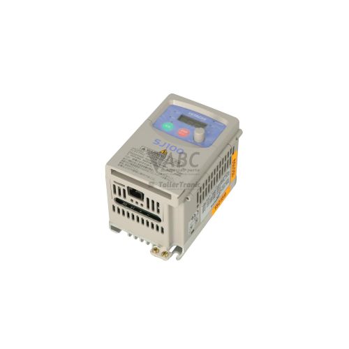
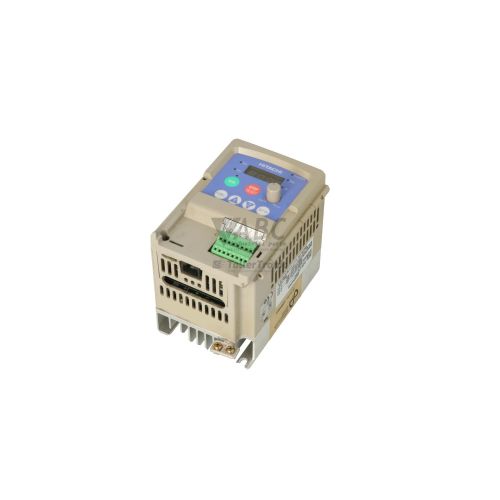
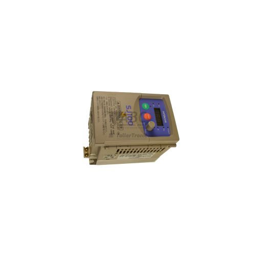
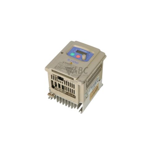
Hitachi SJ100-007HFE Frequency Inverter


Het item werd toegevoegd aan uw offerteaanvraag
Product Information
The Hitachi SJ100-007HFE is a 0.75 kW (1 HP) 400V class 3-phase AC frequency inverter belonging to the Hitachi SJ100 series. Operating on a 380 V AC to 460 V AC 3-phase power supply with a rated input current of 3.3 A and a rated output current of 2.5 A, this compact drive utilizes Sensorless Vector Control (SLV) alongside standard V/f control to deliver high starting torque at low motor speeds. Designed for application across variable speed pumps, industrial fan systems, material handling conveyors, and machine tool spindles, the drive features an output frequency range of 0.1 Hz to 360 Hz and an adjustable carrier frequency between 0.5 kHz and 16 kHz. Physical interface features include an integrated keypad with a 4-digit LED display and a speed potentiometer, complemented by an internal dynamic braking transistor.
For integration into control cabinets and automation networks, the SJ100-007HFE provides 5 programmable digital inputs, 2 digital outputs, 2 analog inputs, and 1 analog output, alongside standard onboard RS-485 Modbus RTU serial communication. Putting a replacement drive into service requires matching terminal wiring and transferring all system-specific operating parameters. Parameter setup can be performed through the onboard digital operator, ProDrive PC configuration software, or handheld digital operators such as the OPE-4S, OPE-J, and SRW-0EX. Because a replacement unit operates on factory defaults, commissioning requires setting motor parameters, control terminal functions, and communication addresses before enabling motor output. ABC Industrial Parts can assist with parameter extraction from existing units or donor hardware to streamline drive replacement and reduce machine downtime.
The SJ100-007HFE incorporates built-in diagnostics centered on its 4-digit LED display and status indicators, including POWER, RUN, PRG, Hz, and A LEDs. Operational state monitoring and fault tracking are accessible through real-time parameters such as output current (d002), output voltage (d003), and terminal status (d005), while historical trip codes (E01 to E60) are stored in trip memory registers d081 through d083. Fault conditions range from external trips and communication timeouts to internal protection events such as overcurrent, overvoltage, or heatsink over-temperature. While external issues like cabling errors or line voltage fluctuations can be resolved in the field, internal failures involving power stage transistors, gate arrays, or control processors require specialized testing, where ABC Industrial Parts provides tested replacement drives and repair options to quickly restore production operations.
Technical Specifications
| Rated Motor Power | 0.75 kW |
| Motor Power | 1 HP |
| Supply Voltage Range | 380 - 460 V AC |
| Supply Phase | 3-Phase |
| Rated Input Current | 3.3 A |
| Maximum Output Voltage | 460 V AC |
| Rated Output Current | 2.5 A |
| Output Frequency Range | 0.1 - 360 Hz |
| Carrier Frequency Range | 0.5 - 16 kHz |
| Control Method | Sensorless Vector Control (SLV) / V/f Control |
| Digital Inputs | 5 |
| Digital Outputs | 2 |
| Analog Inputs | 2 |
| Analog Outputs | 1 |
| Dynamic Braking Chopper | Built-in |
Programming and Configuration
Configuring the Hitachi SJ100-007HFE is supported through both local keypad interfaces and PC-based tools. Primary parameter setup can be performed directly using the built-in digital operator keypad and speed potentiometer or via connected handheld digital operators including the OPE-4S, OPE-J, and SRW-0EX. For comprehensive parameter management and system documentation, Hitachi ProDrive PC software connects via the serial interface, providing parameter editing, offline configuration archiving, and trend monitoring.
Proper commissioning requires setting motor protection settings and control response curves. Parameters such as b012 adjust the electronic thermal overload relay protection level to match connected motor nameplate current, while manual torque boost and carrier frequency parameters optimize output performance. In instances where a drive unit must be restored to default operating state before re-configuration, parameter b084 executes a full parameter initialization.
Communication and System Integration
The SJ100-007HFE comes equipped with an onboard RS-485 serial interface operating Modbus RTU protocol, enabling network control, parameter modification, and status interrogation from central PLCs or HMI panels. Network communication settings, including station address, baud rate, and parity parameters (C071 through C078), are configured using the local keypad or ProDrive software. For fieldbus environments requiring alternative networking protocols, optional expansion cards permit integration into PROFIBUS-DP and DeviceNet networks.
Control circuit wiring interfaces through dedicated terminal blocks providing 5 programmable digital inputs, 2 digital outputs, 2 analog inputs, and 1 analog output. Intelligent digital input terminals can be configured for specific protection functions such as external trip (EXT) or Unattended Start Protection (USP), allowing emergency stop loops and protective safety relays to interface directly with drive control logic.
Diagnostics and Status Indication
Diagnostic monitoring on the SJ100-007HFE utilizes front-panel LED indicators and a 4-digit LED display to present active operating conditions. Dedicated LEDs show control power status (POWER), active drive output status (RUN), programming mode state (PRG), and the active units of the display value (Hz or A). Live operational telemetry can be checked through monitoring parameters including output current (d002), output voltage (d003), and digital terminal state status (d005).
When protective shutdowns occur, the drive displays specific fault codes ranging from E01 to E60. The drive logs trip history within parameters d081, d082, and d083, allowing technicians to review the last three fault events along with operating parameters at the time of the trip. Remote real-time diagnostic monitoring and signal tracing are also supported through ProDrive software.
Status LED Indicators
| LED | Color/Status | Meaning |
|---|---|---|
| POWER | Green - Solid | On when DC bus voltage/control supply power is normal. |
| RUN | Red - Solid | On when drive is in RUN status and supplying output power to motor. |
| PRG / PROGRAM | Solid | On when inverter is in parameter setting/programming mode. |
| Hz | Solid | On when digital display is showing output frequency in Hertz. |
| A | Solid | On when digital display is showing output current in Amperes. |
Replacement and Spare Part Considerations
When sourcing a replacement for a legacy Hitachi SJ100-007HFE drive, verifying physical and electrical specifications is critical. The replacement unit must match the original's 380-460V 3-phase supply requirements and 2.5 A output current rating. Because drive settings are stored in internal EEPROM memory, replacing a unit requires copying operating parameters—such as acceleration profiles, digital I/O functions, and thermal protection values—to the replacement inverter.
For modern control panel retrofits where the legacy SJ100 series is migrated to active product lines, Hitachi designates the WJ200 series (specifically model WJ200-007HFC) as the official successor inverter. While the WJ200 series provides matching 0.75 kW power handling and Sensorless Vector Control capabilities, differences in terminal layouts, mounting dimensions, and parameter structure require wiring adjustments and parameter re-mapping during installation.
Error Codes & Fault Codes
The following error codes may be displayed during operation or diagnostics:
| Code | Name | Description | Possible Cause | Recommended Action |
|---|---|---|---|---|
| E01 | Overcurrent protection during constant speed | Inverter output current exceeded the overcurrent threshold while operating at constant speed. | Short circuit on output, motor overload, sudden load impact, motor locked rotor. | Check motor and wiring for short circuit or ground fault, reduce mechanical load, verify motor parameters. |
| E02 | Overcurrent protection during deceleration | Inverter output current exceeded overcurrent threshold during deceleration. | Deceleration time too short, regenerative energy too high, mechanical binding. | Increase deceleration time, check braking resistor configuration, inspect mechanical system. |
| E03 | Overcurrent protection during acceleration | Inverter output current exceeded overcurrent threshold during acceleration. | Acceleration time too short, motor bound, torque boost set too high. | Increase acceleration time, lower manual torque boost setting, inspect motor and mechanical load. |
| E04 | Overcurrent protection in other conditions | Overcurrent condition detected during stop or other non-standard operating states. | Output short circuit, ground fault, extreme noise interference. | Inspect motor cables and motor insulation. If error persists without motor connected, internal drive power stage fault — return unit for repair. |
| E05 | Overload protection (Thermal trip) | Electronic thermal overload relay protection triggered based on integrated current-time algorithm. | Excessive motor load, electronic thermal level (b012) set incorrectly, prolonged operation at low speed under high load. | Reduce motor load, verify motor current rating against b012 parameter, allow motor/drive time to cool. |
| E06 | Braking resistor overload | Dynamic braking resistor operating ratio exceeded allowable trip limit. | Excessive deceleration rate, high inertia load regenerating energy continuously. | Extend deceleration time, verify dynamic braking usage duty cycle, increase braking resistor capacity if allowed. |
| E07 | Overvoltage protection | DC bus voltage exceeded safe operating limit. | Regenerative energy from motor during deceleration, excessive supply voltage. | Increase deceleration time, install or check dynamic braking resistor, verify mains AC supply voltage. |
| E08 | EEPROM error | Internal memory read/write failure or corrupted memory data. | Electrical noise interference during write operation, internal EEPROM chip hardware degradation. | Internal hardware/memory fault — perform parameter initialization (b084). If fault persists after power cycle, return unit for repair or replace inverter. |
| E09 | Undervoltage protection | DC bus voltage dropped below minimum operating limit. | AC mains supply voltage drop, input phase loss, power supply interruption, faulty main contactor or surge relay. | Check AC input voltage, check main power line fuses and wiring, verify power source stability. |
| E10 | Current sensor error | Internal current detection sensor anomaly or measurement offset fault. | Internal current sensor (CT) hardware failure or control board sensing circuit damage. | Internal hardware fault — turn off power and back on. If fault recurs, replace drive or return for repair. |
| E11 | CPU error | Microprocessor malfunction or control program execution error. | Severe electrical noise, supply transient, internal CPU board hardware failure. | Internal hardware fault — power cycle inverter. If error persists, replace drive or return for repair. |
| E12 | External trip | An external trip signal was received on an intelligent input terminal assigned to EXT. | External protective relay or user device triggered external fault signal. | Inspect external control circuit and connected sensors wired to the EXT terminal, clear external fault condition. |
| E13 | USP error (Unattended Start Protection) | Drive powered up while a RUN command was already active. | Power turned on with RUN switch engaged while USP function active. | Turn off RUN command signal before applying power or resetting the fault. |
| E14 | Ground fault protection | Ground fault current detected between output phase and ground during power-up or run. | Motor winding insulation breakdown, output cable shorted to earth ground. | Check motor insulation resistance with megohmmeter, check output motor cabling for ground short. |
| E15 | Input overvoltage | AC supply input line voltage exceeds maximum rated tolerance. | Supply voltage surge, transformer tap incorrect. | Measure line input AC voltage, ensure line voltage matches drive nameplate specifications. |
| E21 | Inverter over-temperature | Heatsink temperature exceeded safe operating limit. | Cooling fan stopped or degraded, clogged heatsink fins, ambient temperature too high, excessive inverter load. | Clean heatsink, verify cooling fan operation, improve panel ventilation, lower carrier frequency. |
| E22 | CPU communication error | Communication failure between main CPU and sub-processor/option module. | Internal communication failure or loose option board connection. | Internal hardware or expansion interface fault — turn power off, re-seat option card. If fault persists, replace unit or return for repair. |
| E23 | Gate array error | Internal custom ASIC / gate array device error detected. | Internal integrated circuit failure due to component fault or extreme electrical surge. | Internal hardware fault — requires board repair or inverter replacement. Contact Hitachi service. |
| E24 | Phase loss | Input line phase loss or output phase loss detected during operation. | Loose supply wiring, open fuse on one input phase, disconnected motor lead. | Check three-phase supply lines for phase balance and tight wiring; inspect output motor connection. |
| E30 | Driver trip (IGBT driver error) | IGBT power module driver fault or overcurrent/short circuit protection directly on power module. | IGBT short circuit, gate driver IC failure, excessive power stage heat/stress. | Internal hardware failure — power stage / IGBT damaged. Replace inverter or return for repair. |
| E35 | Thermistor trip (PTC error) | External PTC thermistor connected to control terminal detected motor over-temperature condition. | Motor overheating, broken thermistor wiring. | Allow motor to cool, verify motor cooling and load condition, check PTC thermistor wiring. |
| E60 | RS-485 communication error | Timeout or framing error in Modbus / RS-485 serial communication. | Communication cable broken/disconnected, incorrect baud rate or station address, excessive electrical noise on bus. | Check RS-485 wiring and termination resistor, verify communication parameters (C071-C078). |
Frequently Asked Questions
What are the primary power ratings for the Hitachi SJ100-007HFE inverter?
The SJ100-007HFE operates on a 380-460V 3-phase AC supply and delivers a 0.75 kW (1 HP) motor output with a 2.5 A rated output current and a 3.3 A rated input current.
Which software tool and operator keypads support parameter setup?
Parameter programming can be performed via the integrated front-panel keypad, ProDrive PC configuration software over RS-485, or handheld digital operators including the OPE-4S, OPE-J, and SRW-0EX.
What is the recommended successor model for migrating the SJ100-007HFE?
Hitachi recommends migrating from the legacy SJ100 series to the WJ200 series, specifically using the WJ200-007HFC inverter model.
How do I read fault history on the SJ100-007HFE display?
The last three fault events are recorded in parameter registers d081, d082, and d083, accessible via the 4-digit LED display or ProDrive software.
Does the SJ100-007HFE include an integrated braking transistor?
Yes, the drive includes a built-in dynamic braking transistor, allowing direct connection of an external dynamic braking resistor without needing a separate braking module.
Take advantage of our exchange formula
A defective product does not have to be worthless. At ABC Industrial Parts, you can hand in defective products and immediately benefit from a discount on your new purchase. This is a smart way to save money while contributing to a circular economy.
Play it safe with our warranty conditions
Industrial plants prefer to keep running invariably, no matter what. Therefore, it is essential that you can rely on high-quality products and/or sustainable repairs. With our warranty conditions, you can count on certainty, whether you choose new, used or repaired products.
Data backup and recovery
Have you lost valuable parameters or data due to a malfunction while the manufacturer no longer provides support? At ABC Industrial Parts, we help you secure this data, both for common and specific products.
Specific firmware and hardware versions
If you are working with specific hardware or firmware versions that are no longer available from the manufacturer, ABC Industrial Parts is your partner. When making your enquiry, clearly state which versions you need, we will then look at the possibilities of supplying those versions, so that your installations continue to function optimally.
Disclaimer:
We are not an authorised distributor of Hitachi.
Product photos are for illustration purposes only and may differ from the actual product delivered.
Some of the content on this page was created with the help of AI. While we strive to provide accurate and up-to-date information, errors may occur.