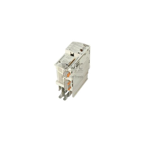
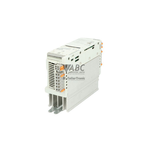
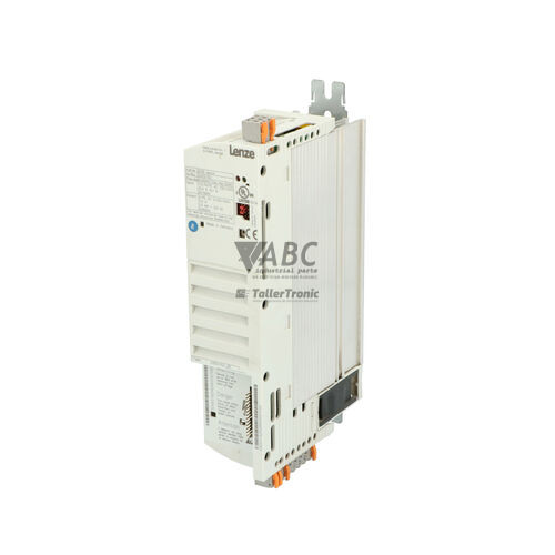
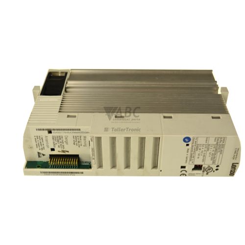
Lenze 00450757 E82EV751_4B 8200 Vector Frequency Inverter 0.75kW



Het item werd toegevoegd aan uw offerteaanvraag
Product Information
The Lenze 00450757 (model E82EV751_4B) is a 0.75 kW frequency inverter from the 8200 Vector product family, engineered for precise velocity and torque regulation of 3-phase AC asynchronous motors. Operating on a 3-phase mains supply from 320 V AC to 528 V AC at 45 to 65 Hz (nominal 3x 400 V / 480 V AC), this drive delivers a continuous rated output current of 2.4 A with a peak output capacity of 3.6 A. Housed in an IP20 cabinet enclosure with a low dissipation power loss of 40 W, the drive supports configurable linear or quadratic V/f characteristic curves as well as sensorless vector control algorithms for dynamic performance in material handling, pumps, fans, and packaging machinery.
System integration relies on a modular front slot architecture that accepts hot-pluggable function modules for discrete control or fieldbus protocols, including CANopen (EMF2171IB, EMF2172IB, EMF2178IB), PROFIBUS DP (EMF2133IB), and LECOM options. Commissioning a replacement unit involves configuring motor parameters and matching network communication settings. Up to four complete parameter sets can be saved in non-volatile internal memory, enabling rapid setup or operational profile switching without a PC. Parameter transfer and setup are executed using Lenze Global Drive Control (GDC) software V4.0 or higher or the plug-in Keypad XT (E82ZBBXC). Technical specialists at ABC Industrial Parts can assist with parameter set extraction and verification when commissioning a spare drive.
Comprehensive diagnostic tools allow maintenance personnel to assess operational status and troubleshoot trip conditions efficiently. Two front-panel LEDs indicate status: a green LED displays readiness or output stage activation, while a red LED illuminates continuously during active TRIP faults or power stage errors. Detailed fault logs can be accessed using keypad display codes C0161 and C0168, GDC software online windows, or fieldbus status words. The drive monitors critical conditions such as DC bus overvoltage and undervoltage (OU, LU), motor phase loss (LP1), overcurrent (OC1, OC2, OC5, OC6), and thermal overload (OH, OH1, OH3, OH4). Hardware defects such as internal microprocessor faults (H05) or EEPROM memory errors (EE0, EER) are not field-serviceable, making repair or a tested exchange unit from ABC Industrial Parts the standard route back to production.
Technical Specifications
| Manufacturer | Lenze |
| Part number | 00450757 |
| Model / type | E82EV751_4B |
| Product family | 8200 Vector |
| Component type | Frequency Inverter |
| Rated power | 0.75 kW |
| Supply voltage range | 3x 320 - 528 V AC (3x 400 / 480 V AC nominal) |
| Rated output current | 2.4 A |
| Peak output current | 3.6 A (150% for 60 s) |
| Output voltage | 0 - 3x Supply Voltage |
| Maximum output frequency | 480 Hz |
| Switching frequency | 8 kHz |
| Power dissipation | 40 W |
| Enclosure protection rating | IP20 |
Programming and Configuration
Programming and parameter adjusting for the Lenze E82EV751_4B frequency inverter are conducted using either the removable Keypad XT (E82ZBBXC) interface panel or Lenze Global Drive Control (GDC) software version 4.0 or higher. The internal control memory holds up to four independent, non-volatile parameter sets. This capability allows operators to pre-program multiple machine recipes or duplicate drive configurations directly through the keypad interface without requiring an external computer on the factory floor.
Through GDC software, engineers can access real-time operational variables, configure custom linear or quadratic V/f characteristics, or set up sensorless vector control algorithms. Drive parameters control motor current limits, switching frequency (up to 8 kHz), carrier adjustments, and electronic motor thermal monitoring via code C0072. Transferring configuration parameters between drives is streamlined by downloading saved parameter files via GDC or cloning memory profiles through the Keypad XT panel.
Communication and System Integration
The Lenze 8200 Vector series uses a modular hardware design featuring a front interface slot for interchangeable communication and I/O function modules. Network integration is achieved by inserting specialized fieldbus modules, such as CANopen modules (EMF2171IB, EMF2172IB, EMF2178IB) for System Bus CAN networks, or the PROFIBUS DP module (EMF2133IB) for connection to higher-level PLC networks.
In addition to fieldbus cards, standard or application I/O function modules can be plugged into the slot to expand hardware terminal control. System diagnostics and operational commands pass through dedicated fieldbus status words, while digital outputs on the inverter can be programmed to signal fault conditions like TRIP activation directly to safety or control circuits.
Diagnostics and Status Indication
Visual status monitoring on the E82EV751_4B front cover is handled by two LED indicators. The green LED signals drive readiness and operation, flashing when the drive is ready with pulse inhibit active, and staying solid when the inverter output stage is active. A solid red LED indicates an active drive fault (TRIP) or an internal power stage fault condition.
Detailed fault evaluation is supported by internal fault history buffers accessible through codes C0161 and C0168 on the Keypad XT display. Alternatively, maintenance technicians can open the online diagnostic window in Lenze Global Drive Control (GDC) or evaluate fieldbus status words to diagnose trip conditions remotely.
Status LED Indicators
| LED | Color/Status | Meaning |
|---|---|---|
| Red LED (TRIP / Fault) | Red - Solid | Active drive fault (TRIP active). If illuminated continuously with green LED off, signifies drive fault condition or internal power stage failure. |
| Green LED (Operation / Ready) | Green - Flashing / Solid | Drive active and operational. Flashing indicates drive ready / pulse inhibit active; solid on indicates output stage active. |
Replacement and Spare Part Considerations
When replacing a failed Lenze 00450757 (E82EV751_4B) frequency inverter, care must be taken to transfer the existing communication or I/O function module from the front interface slot. The base inverter power unit requires an installed function module to connect with fieldbus networks such as CANopen or PROFIBUS DP.
Before restoring power to a replacement unit, motor parameters and fieldbus node addresses must be loaded. Parameters can be copied using the Keypad XT module or loaded via Lenze Global Drive Control (GDC) software V4.0 or higher. For long-term hardware modernization projects where legacy 8200 Vector drives are replaced, the Lenze i550 cabinet inverter series is the recommended modern migration successor.
Error Codes & Fault Codes
The following error codes may be displayed during operation or diagnostics:
| Code | Name | Description | Possible Cause | Recommended Action |
|---|---|---|---|---|
| LU | Undervoltage DC Bus | DC bus voltage dropped below lower threshold limit (approx. 430 V DC for 400V drives). | Mains supply input voltage too low, mains phase failure, line power interruption. | Check input supply voltage, verify mains power fuses and wiring connections. |
| OU | Overvoltage DC Bus | DC bus voltage exceeded upper limit (approx. 770 V DC for 400V drives). | Excessive regenerative energy returned from motor during deceleration, deceleration ramp time too short. | Extend deceleration time, activate overvoltage controller (C0561), or install braking chopper / resistor. |
| OC1 | Short Circuit / Overcurrent during Acceleration | Instantaneous current limit exceeded during speed acceleration. | Short circuit at motor output terminals, motor winding ground fault, acceleration ramp time too short. | Check motor cable and motor windings for insulation fault/short circuit; extend acceleration time. |
| OC2 | Short Circuit / Overcurrent during Deceleration | Instantaneous current limit exceeded during motor deceleration. | Short circuit or ground fault on output, deceleration time too steep. | Check motor cables, motor insulation, and extend deceleration time. |
| OC5 | Overload / Overcurrent in Constant Operation | Instantaneous overcurrent occurred during steady-state constant speed operation. | Sudden mechanical overload, motor stall, or defective motor bearing/load obstruction. | Inspect mechanical system for blockage; check motor size versus load requirements. |
| OC6 | Inverter Overload (I x t) | Continuous overload threshold of inverter power stage exceeded (>150% load for prolonged duration). | Drive dimensioned too small for load profile, continuous operation above nominal current rating. | Reduce motor load duty cycle or upgrade to larger inverter model. |
| OH | Motor Overtemperature | Motor thermistor sensor connected to terminals T1, T2 triggered thermal fault. | Motor overheating due to excessive load, restricted cooling airflow, or thermal sensor fault. | Allow motor to cool, verify cooling fan operation, check motor load and PTC connection. |
| OH1 | Heatsink Overtemperature | Drive heatsink temperature exceeded maximum permissible limit (>90 °C). | Inadequate control cabinet ventilation, ambient temperature too high, clogged heatsink cooling fins. | Clean heatsink, improve enclosure cooling/ventilation, lower switching frequency. |
| OH3 | Inverter Interior Overtemperature | Drive internal ambient temperature limit exceeded (>70 °C). | Control cabinet cooling inadequate or internal fan failed. | Check cabinet fan and heat dissipation inside the enclosure. |
| OH4 | Motor Thermal Overload (I²t) | Internal electronic motor thermal monitoring calculated excessive motor heating. | Continuous low-speed motor operation at high load without external forced cooling fan. | Verify motor thermal settings in C0072; add external forced cooling fan to motor if necessary. |
| EE0 | EEPROM Checksum Error | Internal EEPROM parameter checksum error detected during power-up boot sequence. | Parameter memory corrupted due to power disruption during write sequence or internal hardware memory fault. | Re-initialize parameter set to factory default settings. If fault persists, internal hardware fault — replace the unit. |
| EER | EEPROM Read/Write Access Error | Internal EEPROM hardware communication fault. | Internal control board memory chip hardware defect. | Internal hardware fault — return unit for repair or replace inverter. |
| H05 | Internal Control Failure | Internal microprocessor system hardware fault or internal supply malfunction. | Board-level failure in control circuitry or internal power supply failure. | Internal hardware failure — power cycle drive. If condition remains, replace unit or contact Lenze service. |
| CE0 | Communication Time-out (System Bus / CAN) | Communication time-out reached on System Bus CAN interface. | Fieldbus cable broken, bus termination missing, master controller stopped sending heartbeats. | Check CAN bus wiring, shield connection, terminal resistor termination, and master controller status. |
| CE1 | Function Module Slot Communication Fault | Data communication lost between inverter control board and installed function module in front slot. | Function module loose, poor pin contact, or module defective. | Turn off power, re-seat function module in front slot, ensure lock screws are tight. |
| LP1 | Motor Phase Failure | Phase loss detected on motor output terminals U, V, W. | Disconnected motor wire, blown output line filter fuse, motor winding open circuit. | Inspect motor cabling and output terminal connections. |
Frequently Asked Questions
Which software and keypad interface are compatible with the Lenze E82EV751_4B drive?
The E82EV751_4B drive is programmed using Lenze Global Drive Control (GDC) software version 4.0 or higher, or directly using the plug-in Keypad XT panel (part number E82ZBBXC).
How do I back up or transfer parameters on a Lenze 00450757 inverter?
Up to four parameter sets can be stored internally in non-volatile memory. Parameters can be saved and transferred using GDC software V4.0+ via PC or copied directly using the Keypad XT panel.
What fieldbus communication modules fit into the E82EV751_4B front slot?
The front interface slot accepts CANopen modules (EMF2171IB, EMF2172IB, EMF2178IB), PROFIBUS DP modules (EMF2133IB), as well as LECOM and standard I/O function modules.
What should I do if the inverter displays an EE0 or EER fault code?
EE0 indicates a memory checksum fault during boot; attempt to re-initialize parameters to factory default settings. EER indicates an EEPROM read/write hardware failure. If EE0 persists or EER is displayed, the internal memory chip is defective, requiring board repair or drive replacement.
What is the recommended migration path for the discontinued 8200 Vector inverter family?
The recommended modern successor for replacing 8200 Vector series inverters in control cabinets is the Lenze i550 cabinet inverter series.
Take advantage of our exchange formula
A defective product does not have to be worthless. At ABC Industrial Parts, you can hand in defective products and immediately benefit from a discount on your new purchase. This is a smart way to save money while contributing to a circular economy.
Play it safe with our warranty conditions
Industrial plants prefer to keep running invariably, no matter what. Therefore, it is essential that you can rely on high-quality products and/or sustainable repairs. With our warranty conditions, you can count on certainty, whether you choose new, used or repaired products.
Data backup and recovery
Have you lost valuable parameters or data due to a malfunction while the manufacturer no longer provides support? At ABC Industrial Parts, we help you secure this data, both for common and specific products.
Specific firmware and hardware versions
If you are working with specific hardware or firmware versions that are no longer available from the manufacturer, ABC Industrial Parts is your partner. When making your enquiry, clearly state which versions you need, we will then look at the possibilities of supplying those versions, so that your installations continue to function optimally.
Disclaimer:
We are not an authorised distributor of Lenze.
Product photos are for illustration purposes only and may differ from the actual product delivered.
Some of the content on this page was created with the help of AI. While we strive to provide accurate and up-to-date information, errors may occur.