Lenze 13141956 E82EV302_4C 8200 Vector Frequency Inverter 3.0 kW


Het item werd toegevoegd aan uw offerteaanvraag
Product Information
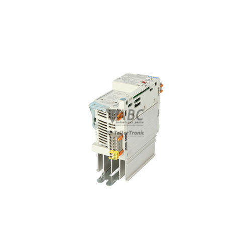
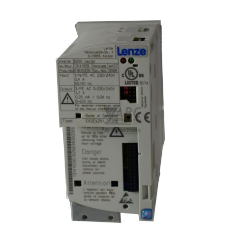
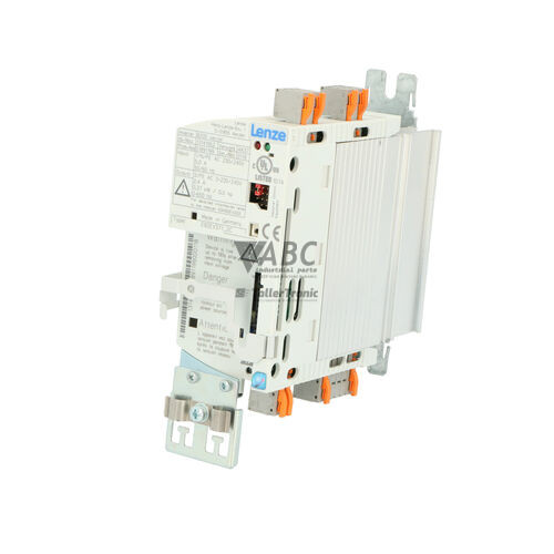
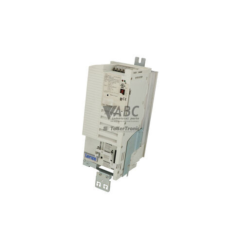
The Lenze 13141956, identified by model designation E82EV302_4C (and referenced as E82EV302K4C), is a 3.0 kW industrial frequency inverter from the 8200 Vector product family designed for speed and torque control of three-phase AC induction motors. Operating on a three-phase supply voltage ranging from 320 to 528 V AC (400/480 V AC nominal), this cabinet-mounted drive provides a rated output current of 7.3 A with an overload capacity of up to 11.0 A for 60 seconds. Built inside an IP20 housing, the unit supports both standard linear/quadratic V/f characteristic control and high-performance sensorless vector control across an output frequency range of 0 to 480 Hz at an 8 kHz switching frequency.
Commissioning a replacement unit requires transferring the parameter configuration and matching the physical fieldbus and control interfaces. The modular construction of the 8200 Vector series separates the core power electronics stage from the control and interface elements. Pluggable E82ZAF series function modules and communication adapters can be transferred directly from an existing unit to the spare. Four internal non-volatile parameter sets stored in EEPROM allow multi-recipe machine configurations, which can be extracted and loaded into a replacement drive using the pluggable E82ZBC XT Keypad Operating Module or via Lenze Global Drive Control (GDC) PC software. Support from ABC Industrial Parts can assist maintenance teams with sourcing tested replacement drives and handling parameter transfers for legacy installations.
System state and operational diagnostic indications are provided via front-panel LEDs, keypad diagnostic codes, and network status words. The dual Red/Green status LED indicates drive readiness with a solid green light, drive inhibition with a flashing green light, active warnings with a flashing red light, and TRIP faults with a solid red light. Diagnostics can be examined directly using keypad codes C0161 for active faults and C0168 for the TRIP fault memory log. External faults like output short circuits (OC1), earth faults (OC2), or line phase failures (LP1) can be investigated on the wiring and motor side, whereas internal micro-controller or memory faults (EEr, H05, H10) point to unserviceable hardware. When internal board faults occur, selecting a tested exchange drive or professional repair through ABC Industrial Parts provides a direct route to minimizing machine downtime.
Technical Specifications
| Manufacturer | Lenze |
| Part Number | 13141956 |
| Model / Type | E82EV302_4C |
| Product Family | 8200 Vector |
| Component Type | Frequency Inverter |
| Rated Power | 3.0 kW |
| Supply Voltage Range | 3x 400/480 V AC (320 - 528 V AC) |
| Rated Output Current | 7.3 A |
| Maximum Output Current | 11.0 A (60 s) |
| Output Frequency Range | 0 - 480 Hz |
| Switching Frequency | 8 kHz |
| Control Method | V/f characteristic control, sensorless vector control |
| Enclosure Rating | IP20 |
| Mounting Type | Cabinet Mounting |
Programming and Configuration
Parameterization and monitoring of the Lenze E82EV302_4C frequency inverter are conducted using either the pluggable E82ZBC XT Keypad Operating Module or the Lenze Global Drive Control (GDC) PC software package. GDC connects to the drive via serial or fieldbus adapters, providing full parameter access, real-time control variable tracing, and offline configuration file management.
The drive contains internal non-volatile EEPROM memory capable of holding four independent parameter sets. This multi-set capability allows machines to switch between different operating profiles or product recipes without re-downloading parameter structures. When commissioning or replacing a unit, parameter sets can be written directly to the memory via keypad or transferred from a PC backup using GDC.
Key drive settings include acceleration ramp time (code C0012), deceleration ramp time (code C0013), and motor thermal monitoring parameters (codes C0084 and C0085). System parameters and fault history logs are accessible via dedicated codes, such as code C0161 for viewing active fault status and code C0168 for inspecting the saved TRIP history.
Communication and System Integration
The Lenze 8200 Vector architecture uses a modular interface slot that separates network communication hardware from the core drive power section. Pluggable E82ZAF series function modules allow the drive to integrate directly into diverse automated control environments without requiring external signal gateways.
Supported communication standards include CANopen, PROFIBUS-DP, DeviceNet, and INTERBUS fieldbus interfaces, alongside standard RS-232 and RS-485 serial communication cards. These modules fit directly into the front expansion slot, allowing real-time transmission of control words, velocity setpoints, operational status words, and diagnostic alerts across the plant network.
Diagnostics and Status Indication
Operational monitoring is conducted through dual-color LED status lights on the drive faceplate, supplemented by keypad parameter display codes and network status word readings. The drive continuously monitors internal hardware conditions, input supply parameters, output currents, and thermal performance.
Active fault conditions are displayed on the optional keypad via parameter code C0161, while code C0168 records historical TRIP events. Fault conditions automatically inhibit drive output to protect connected equipment, requiring parameter reset or power cycling once the root cause is resolved.
Status LED Indicators
| LED | Color/Status | Meaning |
|---|---|---|
| Red LED / Green LED (Drive Status Indicator) | Red/Green - Solid/Flashing | Green ON: Inverter operational / ready; Green FLASHING: Inverter inhibited; Red FLASHING: Warning active; Red ON: TRIP fault active (drive disabled). Internal hardware/EEPROM errors (EEr/Hxx) indicate board failures requiring service. |
Replacement and Spare Part Considerations
When replacing an existing Lenze 13141956 inverter, verify that the replacement drive shares the identical model string (E82EV302_4C) and power specifications (3.0 kW, 7.3 A output current, 400/480 V AC input). Matching the voltage range and power frame ensures physical alignment inside the control cabinet and prevents overload trips during motor operation.
Because the 8200 Vector series separates interface modules from the power chassis, fieldbus options and I/O cards (E82ZAF series) should be swapped onto the replacement drive frame. Parameter settings must be backed up from the existing unit using an E82ZBC XT keypad or GDC software, then loaded into the replacement inverter prior to running the machine.
For plants considering full modernization of legacy drive axes, the Lenze i550 series represents the manufacturer's recommended successor platform. When migrating to the i550 series, cabinet mechanical layouts, wiring configurations, and fieldbus parameters must be updated to match the newer platform design.
Error Codes & Fault Codes
The following error codes may be displayed during operation or diagnostics:
| Code | Name | Description | Possible Cause | Recommended Action |
|---|---|---|---|---|
| OC1 | Short circuit | Short circuit at the output terminals or short circuit to ground. | Short circuit in motor cable or motor windings; motor cable too long or high capacitive current. | Check motor and motor wiring for short circuit or earth fault; check cable length. |
| OC2 | Earth fault | Earth fault at output motor connection. | Ground fault in motor lead or motor frame; moisture in motor connection box. | Check motor insulation resistance and cabling to ground. |
| OC5 | Ixt overload during acceleration | Excessive load or acceleration rate during ramp up. | Acceleration time (C0012) set too short; motor mechanically blocked or overloaded. | Increase acceleration time; check mechanical drive mechanism for blockage. |
| OC6 | Ixt overload during operation | Continuous overload during constant speed operation. | Drive undersized for continuous process load; mechanical binding. | Reduce mechanical load; check motor sizing and drive continuous current rating. |
| OH | Heatsink overtemperature | Inverter heatsink temperature exceeds maximum allowable limit (> 90°C). | Insufficient cooling airflow; ambient temperature too high; fan defective or clogged heatsink. | Clean heatsink cooling fins; verify enclosure ventilation and ambient temperature; replace heatsink fan if broken. |
| OH4 | Motor thermal overload (I2t) | Calculated motor thermal overload state reached. | Continuous low-speed operation under heavy load without forced cooling fan; incorrect motor parameter settings. | Allow motor to cool; check motor thermal rating and parameter settings C0084/C0085. |
| OH7 | Inside temperature high | Internal control board temperature too high. | Excessive control cabinet temperature. | Improve cabinet cooling and ventilation. |
| OU | DC bus overvoltage | DC bus voltage exceeds upper threshold (> 770 V DC / 800 V DC). | Regenerative energy from decelerating heavy load; deceleration time too short; brake chopper or resistor not connected/defective. | Extend deceleration time (C0013); install or check brake resistor / brake chopper. |
| LU | DC bus undervoltage | DC bus voltage fell below minimum operating limit (< 285 V DC for 400V series). | Mains supply voltage drop or failure; blown input fuse; mains phase failure. | Check AC supply voltage, input fuses, and power connections. |
| LP1 | Mains phase failure | Phase loss detected on AC mains supply line. | One mains supply phase disconnected or blown line fuse. | Check supply line voltages across all three phases L1, L2, L3 and replace blown input fuses. |
| CE0 | Communication error system bus (CAN) | Communication interruption on system bus. | Bus cable disconnected, incorrect baud rate, missing termination resistor. | Check CAN bus wiring, shield connections, line termination (120 Ohm), and node addresses. |
| CE1 | Communication error automation module | Communication failure between control card and plug-in automation module. | Module loose or defective; interference on communication bus. | Reseat automation module; check fieldbus connection. |
| CE3 | Communication error keypad | Loss of communication between drive and keypad module during operation. | Keypad unplugged while parameter setting was active. | Reattach keypad firmly; verify connector contacts. |
| EEr | EEPROM memory fault | Internal non-volatile memory read/write failure. | Control board hardware failure or memory corruption. | Internal hardware fault — reload factory default settings; if fault persists, return unit for repair or replace inverter. |
| EFr | External fault | Fault triggered via digital input programmed for external TRIP function. | External monitoring device (e.g. thermal relay, external brake control) tripped. | Check external sensor/device connected to external fault digital input. |
| H05 | Internal hardware error | Control board internal hardware failure detected during self-test. | Internal circuit fault. | Internal hardware fault — power cycle drive; if persistent, return unit for repair or replace inverter. |
| H10 | Internal routine fault | Internal software or micro-controller execution error. | Firmware error or board noise fault. | Internal hardware/firmware fault — power cycle drive; if fault reoccurs, replace or service the drive. |
| NMAX | Speed threshold exceeded | Actual motor frequency exceeded maximum limits. | Motor driven externally by load or incorrect gain tuning in vector control mode. | Check speed controller parameters and overspeed mechanics. |
Frequently Asked Questions
What software and keypad options are available for configuring the Lenze 13141956 drive?
The inverter can be configured using the pluggable Lenze E82ZBC XT Keypad Operating Module or via PC using Lenze Global Drive Control (GDC) software.
What do the Red and Green status LEDs indicate during operation?
A solid green light indicates normal operation, a flashing green light shows drive inhibit, a flashing red light alerts to an active warning, and a solid red light signals an active TRIP fault.
Which fieldbus interfaces are supported by the E82EV302_4C inverter?
The drive supports CANopen, PROFIBUS-DP, DeviceNet, INTERBUS, and RS-232/485 serial interfaces using pluggable E82ZAF series function modules.
How do I check fault history and current trip status on the inverter?
Active fault conditions can be viewed via keypad code C0161, while historical TRIP events are stored in the fault memory log accessible under code C0168.
What action is required if the drive displays an EEr, H05, or H10 error code?
These codes indicate internal hardware or EEPROM faults. First attempt to cycle power or reload factory defaults. If the fault persists, internal circuit failure is present and the inverter must be repaired or replaced.
What is the recommended modern replacement series for the legacy 8200 Vector drive?
The Lenze i550 series is the recommended modern successor family for replacing legacy 8200 Vector frequency inverters.
Take advantage of our exchange formula
A defective product does not have to be worthless. At ABC Industrial Parts, you can hand in defective products and immediately benefit from a discount on your new purchase. This is a smart way to save money while contributing to a circular economy.
Play it safe with our warranty conditions
Industrial plants prefer to keep running invariably, no matter what. Therefore, it is essential that you can rely on high-quality products and/or sustainable repairs. With our warranty conditions, you can count on certainty, whether you choose new, used or repaired products.
Data backup and recovery
Have you lost valuable parameters or data due to a malfunction while the manufacturer no longer provides support? At ABC Industrial Parts, we help you secure this data, both for common and specific products.
Specific firmware and hardware versions
If you are working with specific hardware or firmware versions that are no longer available from the manufacturer, ABC Industrial Parts is your partner. When making your enquiry, clearly state which versions you need, we will then look at the possibilities of supplying those versions, so that your installations continue to function optimally.
Disclaimer:
We are not an authorised distributor of Lenze.
Product photos are for illustration purposes only and may differ from the actual product delivered.
Some of the content on this page was created with the help of AI. While we strive to provide accurate and up-to-date information, errors may occur.