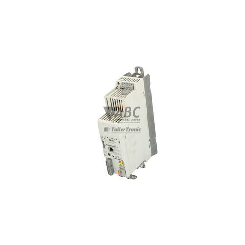
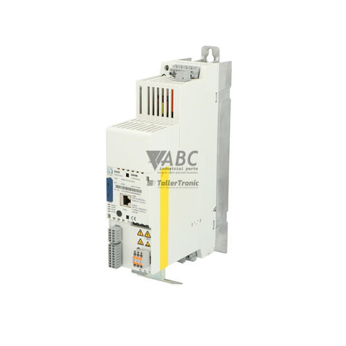
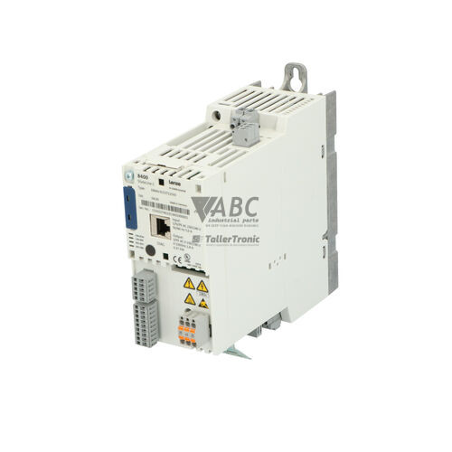
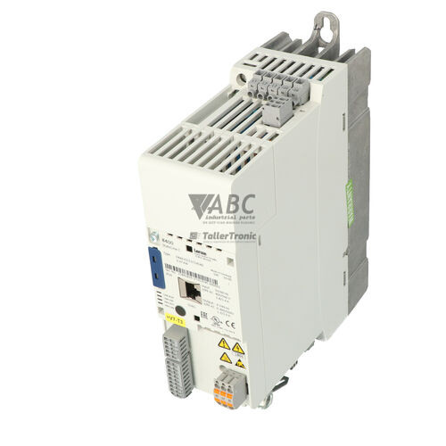
Lenze E84AVSCE2512SX0 8400 StateLine C Frequency Inverter


Het item werd toegevoegd aan uw offerteaanvraag
Product Information
The Lenze E84AVSCE2512SX0 is a 0.25 kW frequency inverter belonging to the 8400 StateLine C series, designed for controlled speed and torque management of AC motors in industrial automation. Operating on single-phase or three-phase 230 V AC mains networks across an input range of 180 V to 264 V AC, this compact IP20 panel-mount unit supplies a three-phase output from 0 to 230 V AC at a rated current of 1.7 A. Built to manage heavy-duty startup requirements, it features a 150% overload capability for up to 60 seconds with peak currents reaching 2.55 A. The drive supports both V/f characteristic control and sensorless vector control (SLVC) over an output frequency range of 0 to 599 Hz with an 8 kHz switching frequency. Integrated Safe Torque Off (STO) functional safety compliant with SIL 3 and PL e standards comes standard to streamline machine safety compliance without requiring external safety contactors.
System integration and fieldbus connectivity are flexible, featuring an onboard CANopen system bus terminal alongside support for optional communication modules such as PROFINET (E84AYCER), PROFIBUS (E84AYCPM), or EtherCAT (E84AYCET). Software configuration is conducted through Lenze EASY Starter or L-force Engineer, while local operating parameters can be accessed via the optional X400 Keypad E84AVYD. Commissioning a spare unit is exceptionally efficient due to the pluggable Lenze Memory Module E84AYM. By storing all drive settings directly on this removable hardware memory chip, parameters can be transferred directly to a replacement inverter without using a PC or configuration software. Technicians installing a spare unit sourced from ABC Industrial Parts can simply move the existing memory chip to the new drive to align configurations immediately.
Real-time operation and system health are indicated through four dedicated front panel LEDs: DRV-READY, DRV-ERR, CAN-RUN, and CAN-ERR. Detailed diagnostic tracking is available via parameter C00150 for active faults and parameter group C0016x for the non-volatile fault history log, accessible via the front X400 diagnostic connector. First-line troubleshooting should include checking mains input power, dual-channel 24 V STO safety signals, motor wiring insulation, and fieldbus termination resistors (120 Ohm). If diagnostic testing indicates unrecoverable hardware faults such as internal power board failure (H01) or persistent internal thermal overload (OHI), the unit contains non-serviceable internal electronics. In these situations, exchanging the unit or choosing specialized repair through ABC Industrial Parts provides a reliable path back to full production.
Technical Specifications
| Manufacturer | Lenze |
| Part Number | E84AVSCE2512SX0 |
| Model / Type | 8400 StateLine C |
| Component Type | Frequency Inverter |
| Product Family | 8400 StateLine |
| Rated Power | 0.25 kW |
| Supply Voltage Range | 180 - 264 V AC |
| Supply Configuration | 1/N/PE AC 230 V / 3/PE AC 230 V |
| Rated Output Current | 1.7 A |
| Max Output Current (60s) | 2.55 A |
| Output Voltage Range | 3x 0 - 230 V AC |
| Output Frequency Range | 0 - 599 Hz |
| Switching Frequency | 8 kHz |
| Control Modes | V/f characteristic control, Sensorless Vector Control (SLVC) |
| Integrated Fieldbus | CANopen |
| Digital Inputs | 5 |
| Digital Outputs | 1 |
| Analog Inputs | 1 |
| Analog Outputs | 1 |
| Protection Rating | IP20 |
| Integrated Safety | Safe Torque Off (STO) SIL 3 / PL e |
Programming and Configuration
Engineering and commissioning of the Lenze E84AVSCE2512SX0 drive are managed using Lenze EASY Starter and L-force Engineer software packages. Connection between the engineering PC and the inverter is established via the diagnostic X400 interface on the front panel. Software parameters control motor profile settings, control mode selection (V/f or Sensorless Vector Control), acceleration and deceleration ramps, I/O terminal mapping, and fieldbus communication addresses. Diagnostic parameter C00150 records active fault conditions, while parameter buffer C0016x provides full access to historical fault logs stored in non-volatile memory.
To simplify drive maintenance and replacement, the unit uses the pluggable Lenze Memory Module E84AYM. All parameter configurations, application data, and motor tuning settings are stored directly on this interchangeable chip. In the event of a hardware exchange, the memory module can be unplugged from the faulty drive and inserted into the replacement inverter. This physical parameter transfer completes drive setup instantly without requiring software connections, PC cables, or manual parameter entry. Local parameter monitoring and drive adjustments can also be performed using the optional X400 Keypad E84AVYD.
Communication and System Integration
The E84AVSCE2512SX0 drive incorporates an onboard CANopen system bus interface for real-time motion integration and control. Supporting operational, pre-operational, and stopped network states, the CANopen interface facilitates high-speed speed synchronization, command transmission, and diagnostic parameter monitoring. Front panel LEDs CAN-RUN and CAN-ERR deliver immediate feedback regarding operational status, network sync, and communication guard errors. Standard 120 Ohm termination resistors must be configured at the physical ends of the CAN network bus to maintain signal stability.
For integration into alternative fieldbus structures, the 8400 StateLine C architecture features a modular communication expansion slot. Optional plug-in interfaces allow the drive to communicate over PROFINET (E84AYCER), PROFIBUS (E84AYCPM), and EtherCAT (E84AYCET) networks. I/O wiring is connected through plug-in screw terminal strips, incorporating 5 digital inputs, 1 digital output, 1 analog input, and 1 analog output for direct connection to sensors, switches, and supervisory control systems.
Diagnostics and Status Indication
Real-time visual monitoring for the Lenze E84AVSCE2512SX0 frequency inverter is provided through four multi-color LED indicators on the front housing. These LEDs display drive readiness (DRV-READY), active drive faults (DRV-ERR), CANopen bus execution (CAN-RUN), and CANbus network errors (CAN-ERR). Advanced diagnostic evaluation can be conducted via the X400 connector using EASY Starter software, granting access to real-time operating variables, active fault parameter C00150, and historical fault log parameter group C0016x.
Status LED Indicators
| LED | Color/Status | Meaning |
|---|---|---|
| DRV-READY | Green - Solid / Flashing / Off | Solid = Drive ready for operation / active; Flashing = Switched on, controller inhibit active; Off = Internal fault or missing supply voltage |
| DRV-ERR | Red - Solid / Flashing / Off | Flashing = Warning / active fault requiring reset; Solid = Internal hardware fault or trip condition; Off = No fault present |
| CAN-RUN | Green - Solid / Flashing / Blinking | Solid = CANopen Operational; Flashing = Pre-operational; Blinking = Stopped state |
| CAN-ERR | Red - Solid / Flashing / Off | Solid = CANbus Off / Hardware CAN error; Flashing = CAN communication error / guard fault; Off = Normal CAN communication |
Replacement and Spare Part Considerations
When selecting a replacement drive for an existing installation, verify that the exact part number E84AVSCE2512SX0 matches the original unit's power rating (0.25 kW) and output current (1.7 A). Parameter alignment on a replacement unit is straightforward: by removing the E84AYM memory module from the original drive and plugging it into the replacement inverter, all application parameters, bus addresses, and motor data are instantly restored without needing software downloads or PC configurations.
While the Lenze 8400 StateLine series has entered phase-out status—with Lenze designating the i550 cabinet inverter series (i55AE125B10010000S) as the official successor for new panel designs—using a direct E84AVSCE2512SX0 replacement unit remains the most effective solution for existing machinery. A direct hardware replacement avoids the need for panel re-engineering, wiring modifications, STO safety re-certification, or PLC communication changes.
Error Codes & Fault Codes
The following error codes may be displayed during operation or diagnostics:
| Code | Name | Description | Possible Cause | Recommended Action |
|---|---|---|---|---|
| OC1 | Short circuit / Overcurrent | Output current exceeds threshold due to short circuit or excessive motor acceleration rate. | Short circuit in motor cable, motor winding fault, acceleration ramp too short. | Check motor and motor wiring for short circuit / earth fault; increase acceleration time; verify motor parameters. |
| OC2 | Earth fault / Ground fault | Ground fault detected on motor output phases. | Insulation failure in motor cable or motor, excessive cable capacitance. | Measure insulation resistance of motor cable and motor windings; check output cable length limits. |
| OU | DC-bus overvoltage | DC bus voltage exceeded upper limit. | Regenerative energy from motor during deceleration, braking resistor not connected or defective, main supply voltage too high. | Increase deceleration time; install or inspect braking resistor; check mains supply voltage. |
| LU | DC-bus undervoltage | DC bus voltage fell below minimum operation threshold. | Mains supply failure, voltage drop under load, fuse blown. | Check mains voltage, fuses, and power connections. |
| OH | Heatsink overtemperature | Inverter heatsink temperature exceeds limit. | Ambient temperature too high, fan failure, blocked ventilation slots, continuous overload. | Clean heatsink, ensure adequate cooling airflow, verify ambient temperature, check load profile. |
| OHI | Internal overtemperature | Internal power module / control circuit temperature limit exceeded. | Excessive internal heating, ambient temperature above specification, hardware component aging. | Improve cooling inside enclosure. If problem persists at normal temperature, internal board hardware fault exists — return unit for repair. |
| OHE | Motor thermal overload | Motor temperature sensor reported overtemperature. | Motor overloaded, cooling fan on motor failed, sensor wire broken. | Allow motor to cool, check mechanical load and motor cooling fan, inspect motor thermal sensor wiring. |
| Ixt | I*t thermal motor overload | Calculated I*t value for motor thermal protection reached trip threshold. | Continuous operation above rated motor current. | Check motor dimensioning, reduce load, inspect mechanical system for binding. |
| CE0 | CANopen communication error | Communication failure on CANopen / system bus interface. | Bus cable disconnected, incorrect termination resistor, baud rate mismatch, CAN master offline. | Check CAN cabling, termination switches (120 Ohm), baud rate settings, and PLC status. |
| STO | Safe Torque Off active | Safe Torque Off safety function triggered or channel discrepancy. | Safety circuit opened, dual-channel inputs mismatched, STO wiring open. | Verify STO input signals (24V on both channels); check safety relay / safety PLC outputs. |
| H01 | Internal hardware fault | Power board or control board internal error detected during self-test. | Internal component failure, memory failure, corrupted internal EEPROM. | Internal hardware fault — return unit for service or replace inverter. |
Frequently Asked Questions
How do I transfer parameters to a replacement Lenze E84AVSCE2512SX0 drive?
Parameters can be transferred instantly by unplugging the Lenze Memory Module E84AYM from the original drive and inserting it into the replacement inverter. This clones all motor settings, communication profiles, and parameters without requiring a PC or commissioning software.
What safety capabilities are integrated into the E84AVSCE2512SX0 inverter?
The drive includes integrated Safe Torque Off (STO) functional safety certified to SIL 3 according to IEC 61508 and PL e according to EN ISO 13849-1, allowing safety shutdowns without external power contactors.
Which software tools are used to configure and diagnose this drive?
Lenze EASY Starter and L-force Engineer software tools are used for parameter configuration and diagnostic monitoring via a PC connected to the front panel X400 diagnostic port.
What fieldbus protocols does the 8400 StateLine C inverter support?
The drive features a native CANopen system bus interface onboard and supports optional plug-in modules for PROFINET (E84AYCER), PROFIBUS (E84AYCPM), and EtherCAT (E84AYCET).
What is the recommended successor drive if upgrading to a current series?
Lenze designates the i550 cabinet frequency inverter series, specifically model i55AE125B10010000S, as the official successor drive series for new machine designs.
Take advantage of our exchange formula
A defective product does not have to be worthless. At ABC Industrial Parts, you can hand in defective products and immediately benefit from a discount on your new purchase. This is a smart way to save money while contributing to a circular economy.
Play it safe with our warranty conditions
Industrial plants prefer to keep running invariably, no matter what. Therefore, it is essential that you can rely on high-quality products and/or sustainable repairs. With our warranty conditions, you can count on certainty, whether you choose new, used or repaired products.
Data backup and recovery
Have you lost valuable parameters or data due to a malfunction while the manufacturer no longer provides support? At ABC Industrial Parts, we help you secure this data, both for common and specific products.
Specific firmware and hardware versions
If you are working with specific hardware or firmware versions that are no longer available from the manufacturer, ABC Industrial Parts is your partner. When making your enquiry, clearly state which versions you need, we will then look at the possibilities of supplying those versions, so that your installations continue to function optimally.
Disclaimer:
We are not an authorised distributor of Lenze.
Product photos are for illustration purposes only and may differ from the actual product delivered.
Some of the content on this page was created with the help of AI. While we strive to provide accurate and up-to-date information, errors may occur.