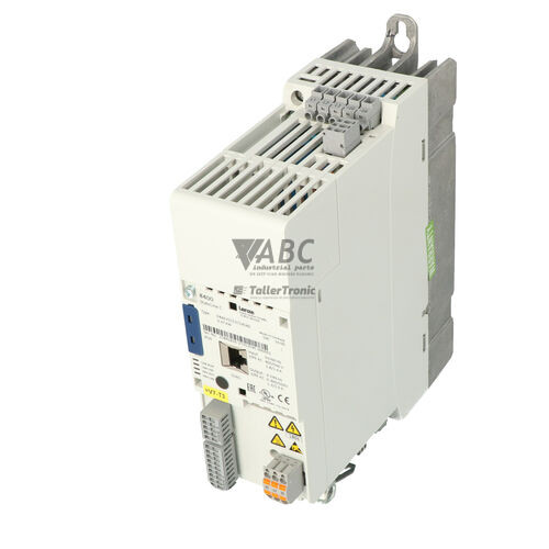
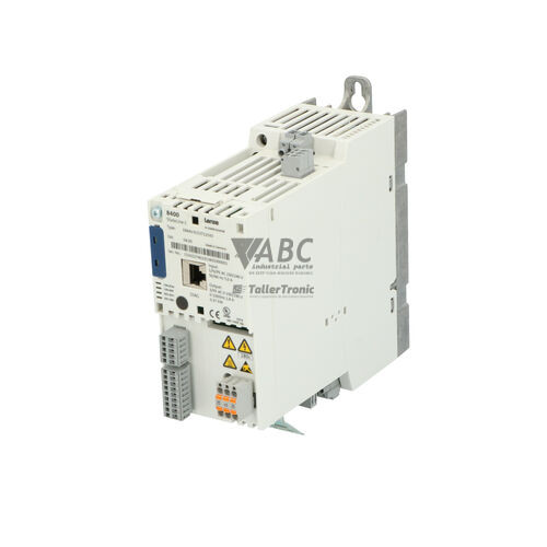
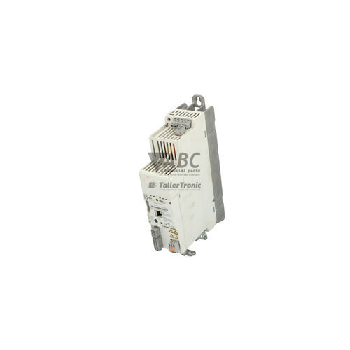
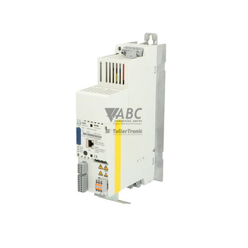
Lenze E84AVSCE3714SB0 8400 StateLine C Frequency Inverter



Het item werd toegevoegd aan uw offerteaanvraag
Product Information
The Lenze E84AVSCE3714SB0 is a 0.37 kW cabinet-mounted frequency inverter from the Lenze 8400 StateLine C series designed for dynamic motion control and precise speed regulation across industrial drive applications. Operating on a 3-phase AC supply voltage range of 320 V to 550 V with an IP20 protection rating, this drive delivers a rated output current of 1.3 A with an output frequency range up to 599 Hz. Motor control is supported through configurable linear or quadratic V/f characteristics as well as Sensorless Vector Control (SLVC). The inverter incorporates functional safety via built-in Safe Torque Off (STO) certified to SIL 3 / PL e standards, and includes an integrated brake chopper for dynamic braking operations.
Connecting and installing a replacement E84AVSCE3714SB0 drive involves aligning local control wiring, network connections, and parameter storage. The hardware interface provides 5 digital inputs, 1 digital output, 2 analog inputs, and 1 analog output, alongside onboard CANopen fieldbus support and an expansion slot for optional fieldbus communication modules such as PROFIBUS (E84AYCPM), PROFINET (E84AYCER), EtherCAT (E84AYCET), or EtherNet/IP (E84AYCEO). Commissioning and parameter setup can be managed through Lenze L-force Engineer or EASY Starter engineering tools connected via the EWLDA USB diagnostic adapter, or directly using the Keypad XT (E84AYKXT). Rapid field replacement without engineering software is enabled by transferring the removable Memory Module from the original inverter directly into the spare unit, restoring all operational settings offline. ABC Industrial Parts can assist in sourcing pre-tested replacement units and compatible options to ensure smooth system deployment.
Diagnostic monitoring and troubleshooting on the E84AVSCE3714SB0 are visually signaled via status LEDs and detailed TRIP codes. Front panel LEDs display status for DRIVE READY (RDY), DRIVE ERROR (ERR), CAN-RUN, and CAN-ERR, giving clear indicators for drive enable state, active trip conditions, hardware errors, and fieldbus communication health. Fault memory logging records historical events accessible through engineering tools or the Keypad XT display. First-line troubleshooting for common trips includes checking line voltage stability for DC bus undervoltage (LU), verifying motor and motor wiring for short circuit or overcurrent (OC1), and inspecting cabinet cooling or heatsink cleanliness for overtemperature conditions (OH, IOH). Internal hardware failures indicated by a persistent FAIL trip code or solid red error indication are non-repairable on site; in these cases, replacing the unit or arranging a tested exchange through ABC Industrial Parts provides a direct route back to normal operation.
Technical Specifications
| Rated Power | 0.37 kW |
| Supply Voltage Range | 320 - 550 V AC |
| Rated Output Current | 1.3 A |
| Output Frequency Range | 0 - 599 Hz |
| Switching Frequency | 8 kHz |
| Control Method | V/f control, Sensorless Vector Control (SLVC) |
| Safety Function | Safe Torque Off (STO, SIL 3 / PL e) |
| Protection Rating | IP20 |
| Mounting Style | Cabinet Installation |
| Integrated System Fieldbus | CANopen |
| Integrated Brake Chopper | Yes |
| Digital Inputs | 5 |
| Digital Outputs | 1 |
| Analog Inputs | 2 |
| Analog Outputs | 1 |
Programming and Configuration
Drive setup and parameter management for the Lenze E84AVSCE3714SB0 are performed using Lenze L-force Engineer or EASY Starter software packages. Connection between a PC and the inverter is established using the Lenze EWLDA USB Diagnostic Adapter. Alternatively, field parameter adjustments and manual control can be performed directly at the drive using the pluggable Keypad XT (E84AYKXT), which presents diagnostic messages and operational data in plain text.
The drive features a pluggable Memory Module system that stores complete parameter configurations offline. This hardware memory allows parameters to be cloned or backed up without requiring a powered engineering connection. During unit replacement, transferring the Memory Module from the existing drive to the spare hardware restores all motor data, control curves, and safety settings instantly.
Communication and System Integration
System integration with top-level PLCs and automation networks is facilitated by the E84AVSCE3714SB0's onboard CANopen interface. This integrated fieldbus supports operational, pre-operational, and stopped network states with status indicated by the CAN-RUN and CAN-ERR LED indicators. Proper bus termination with 120 Ohm resistors and correct baud rate matching are required for stable CAN communication.
For applications requiring industrial Ethernet or traditional fieldbus communication, the drive includes a modular extension slot. This slot accommodates optional expansion modules, including PROFIBUS DP (E84AYCPM), PROFINET (E84AYCER), EtherCAT (E84AYCET), and EtherNet/IP (E84AYCEO). Hardwired control wiring is terminated across discrete terminals providing 5 digital inputs, 1 digital output, 2 analog inputs, and 1 analog output.
Diagnostics and Status Indication
Real-time status monitoring on the E84AVSCE3714SB0 is provided through visual LED indicators and internal diagnostic registers accessible via fieldbus or connected software. Operational state, fault conditions, and fieldbus status are actively indicated on the front panel. Internal diagnostic logs record fault history in a dedicated TRIP buffer for root-cause analysis.
Diagnostic text and fault codes can be read directly using the Keypad XT (E84AYKXT) or through the EASY Starter diagnostic software. The integrated LED indicators provide immediate visual feedback regarding drive enable status, active fault conditions, and CANopen network state.
Status LED Indicators
| LED | Color/Status | Meaning |
|---|---|---|
| DRIVE READY / RDY | Green / Red - Solid / Blinking | Green ON = Inverter ready / enabled; Green Blinking = Inverter ready but disabled; OFF = Not ready or power missing; Fast flashing Red/Green = Initialization or fault state |
| DRIVE ERROR / ERR | Red - Solid / Blinking | Red ON = Active TRIP fault condition; Red Blinking = Warning active; Continuous solid red = Unrecoverable hardware fault requiring device service |
| CAN-RUN | Green - Solid / Blinking / Single Flash | Green ON = CANopen operational state; Green Blinking = CANopen pre-operational state; Single flash = CANopen stopped state |
| CAN-ERR | Red - Solid / Blinking / Off | Red ON = CANopen bus off; Red Blinking = CANopen controller error frame / limit reached; OFF = Normal CANopen operation |
Replacement and Spare Part Considerations
When replacing a Lenze E84AVSCE3714SB0 frequency inverter, matching the exact model number ensures identical electrical ratings, including the 0.37 kW output capacity and 320 V to 550 V AC supply range. Mechanical compatibility is simplified by the standard IP20 cabinet-mounting form factor.
Field replacement is streamlined by transferring the existing pluggable Memory Module to the replacement drive, eliminating the need to re-enter motor parameters or reconfigure fieldbus settings using a PC. Any optional communication modules installed in the extension slot must be re-seated carefully in the replacement unit to maintain network integration.
As the Lenze 8400 StateLine series transitions through its product lifecycle, direct replacement units remain effective for maintaining existing machine designs without panel modifications. For long-term migration strategies, the Lenze i550 cabinet frequency inverter series represents the successor generation.
Error Codes & Fault Codes
The following error codes may be displayed during operation or diagnostics:
| Code | Name | Description | Possible Cause | Recommended Action |
|---|---|---|---|---|
| OC1 | Short circuit / overcurrent | Output peak current exceeded the internal hardware limit. | Short circuit on motor terminals, earth fault, acceleration time set too short, motor overload. | Check motor and motor cables for short circuit or earth fault. Increase acceleration ramp times. |
| OC5 | I2t motor overload | Calculated motor thermal load limit exceeded. | Continuous motor overload, incorrect motor rated current settings. | Check mechanical drive system load. Verify motor parameter data in inverter configuration. |
| OU | DC bus overvoltage | Intermediate circuit DC bus voltage exceeded maximum allowable threshold. | Excessive regenerative energy during deceleration, deceleration ramp time too short, brake resistor disconnected or faulty. | Extend deceleration time (decel ramp). Verify external brake resistor connection and internal brake chopper configuration. |
| LU | DC bus undervoltage | DC link voltage dropped below minimum operating limit. | Mains supply voltage too low, mains phase failure, power interruption during operation. | Check AC mains supply voltage, fuses, and line contactor. |
| OH | Heatsink overtemperature | Inverter heatsink temperature exceeded maximum threshold limit. | Insufficient cooling airflow, ambient temperature too high, dirty heatsink, fan fault. | Clean heatsink fins, ensure adequate cabinet ventilation, verify fan operation. |
| OH4 | Motor overtemperature (PTC / TK) | Motor thermal contact or PTC thermistor trip. | Motor thermal overload, lack of forced cooling, defective motor PTC sensor circuit. | Allow motor to cool down. Check motor loading and PTC sensor wiring at terminal block. |
| IOH | Inverter internal overtemperature | Internal temperature inside control module exceeded maximum limit. | Excessive ambient temperature inside control cabinet. | Improve control cabinet cooling. |
| CE0 | CANopen communication failure | CANopen system bus error or Bus-Off state. | Interrupted CAN connection, incorrect baud rate, missing bus termination resistors, fieldbus master timeout. | Check CAN wiring, termination switches (120 Ohm), baud rate, and master status. |
| CE1 | Communication module fault | Communication fault between inverter control board and optional fieldbus module slot. | Module disconnected, improper seat in slot, communication loss with master PLC. | Check module mechanical mounting in slot. Verify fieldbus wiring and master PLC status. |
| PMax | Maximum power limit exceeded | Electrical power limit exceeded. | Severe overload on motor shaft. | Reduce mechanical load or increase inverter power rating. |
| FAIL | System hardware fault | Internal control hardware failure detected during self-test or operation. | Internal electronic component failure, damaged board. | Internal hardware fault — power cycle unit; if persistent, unit is non-repairable in field and requires replacement or factory repair. |
Frequently Asked Questions
How do I transfer parameter settings when replacing a Lenze E84AVSCE3714SB0 inverter?
Parameter settings can be transferred by physically moving the pluggable Memory Module from the existing drive to the replacement unit. This transfers all stored configuration data, motor parameters, and fieldbus settings without needing engineering software. Alternatively, configuration can be backed up and uploaded using Lenze EASY Starter or L-force Engineer with a EWLDA USB diagnostic adapter.
What engineering software is compatible with the Lenze E84AVSCE3714SB0?
Configuration and diagnostic tasks are supported by Lenze L-force Engineer and Lenze EASY Starter software packages. Physical connection to a PC requires the Lenze EWLDA USB Diagnostic Adapter, while direct handheld operation can be performed using the Keypad XT (E84AYKXT).
What integrated safety features does the E84AVSCE3714SB0 provide?
The inverter features integrated Safe Torque Off (STO) certified to SIL 3 per IEC 61508 and PL e per EN ISO 13849-1. This function allows safe torque disconnection without interrupting main line supply power.
Which fieldbus protocols are supported by the E84AVSCE3714SB0?
Onboard CANopen communication is standard. Additionally, the drive features a modular expansion slot that accepts optional modules for PROFIBUS DP (E84AYCPM), PROFINET (E84AYCER), EtherCAT (E84AYCET), and EtherNet/IP (E84AYCEO).
What should I check if the E84AVSCE3714SB0 displays fault code OC1?
Fault code OC1 indicates output overcurrent or a short circuit. Inspect the motor and motor cables for phase-to-phase short circuits or earth faults, verify mechanical loading on the drive, and check if acceleration ramp times need to be increased.
What is the recommended successor series for the Lenze 8400 StateLine C inverter?
The recommended successor line for cabinet installation is the Lenze i550 cabinet frequency inverter series.
Take advantage of our exchange formula
A defective product does not have to be worthless. At ABC Industrial Parts, you can hand in defective products and immediately benefit from a discount on your new purchase. This is a smart way to save money while contributing to a circular economy.
Play it safe with our warranty conditions
Industrial plants prefer to keep running invariably, no matter what. Therefore, it is essential that you can rely on high-quality products and/or sustainable repairs. With our warranty conditions, you can count on certainty, whether you choose new, used or repaired products.
Data backup and recovery
Have you lost valuable parameters or data due to a malfunction while the manufacturer no longer provides support? At ABC Industrial Parts, we help you secure this data, both for common and specific products.
Specific firmware and hardware versions
If you are working with specific hardware or firmware versions that are no longer available from the manufacturer, ABC Industrial Parts is your partner. When making your enquiry, clearly state which versions you need, we will then look at the possibilities of supplying those versions, so that your installations continue to function optimally.
Disclaimer:
We are not an authorised distributor of Lenze.
Product photos are for illustration purposes only and may differ from the actual product delivered.
Some of the content on this page was created with the help of AI. While we strive to provide accurate and up-to-date information, errors may occur.