Lust 1866-2101 VF1205M Frequency Inverter


Het item werd toegevoegd aan uw offerteaanvraag
Product Information
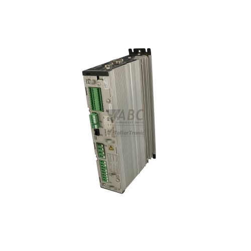
The Lust Antriebstechnik 1866-2101, model designation VF1205M,C13,S35,G16,PT1,BR1, is a 0.55 kW AC frequency inverter from the VF1000M product family designed for precise speed control of 3-phase asynchronous motors. Operating from a 230 V AC single-phase or multi-phase supply, this drive delivers a continuous output current of 2.3 A across an output voltage range of 0 to 230 V AC and supports maximum output frequencies up to 400 Hz. The drive employs configurable V/f characteristic control with adjustable switching frequencies up to 16 kHz to ensure low-noise motor operation. Hardware build options integrated into this specific model include Option C13 for CANopen fieldbus communication, Option BR1 featuring an internal dynamic braking chopper transistor, and Option PT1 for direct motor PTC thermistor monitoring.
Integrating a replacement 1866-2101 inverter requires connecting control wiring, fieldbus cables, and power connections. The terminal arrangement supports five programmable digital inputs, one digital relay output, and one analog setpoint input alongside dedicated connections for the CANopen network operating at speeds up to 500 kbit/s. An RS-232 interface allows connection to DriveManager configuration software, while external braking resistors attach directly to the BR1 terminals (+UG, RB) and motor thermistor sensors connect to the PT1 terminals. Putting a replacement drive into service is rarely plug-and-run; the complete application parameter set stored in non-volatile EEPROM must be transferred to the replacement unit using either the plug-in KP100 operator panel or DriveManager software. Support from ABC Industrial Parts can assist maintenance teams with parameter setup and sourcing fully tested replacement units.
Drive operation and fault states are indicated visually via the red and green H1 and H2 status LEDs located on the KP100 keypad or display panel, as well as numerical E-xx error codes shown on the keypad display. Diagnostic analysis is further supported by the internal non-volatile fault history register and the DriveManager software interface. First-line troubleshooting for tripped drives includes checking the main 230 V AC power supply, verifying phase-to-phase and phase-to-ground isolation on motor outputs, inspecting external braking resistor resistance across BR1 terminals, and testing motor thermistor continuity at PT1 terminals. When internal microprocessor or memory failures occur, board-level repairs are not field-serviceable, making a tested exchange unit from ABC Industrial Parts the most reliable path to restore production line operation.
Technical Specifications
| Manufacturer | Lust Antriebstechnik |
| Part Number | 1866-2101 |
| Model / Type Designation | VF1205M,C13,S35,G16,PT1,BR1 |
| Product Family | VF1000M |
| Component Type | Frequency Inverter |
| Supply Voltage | 230 V AC |
| Rated Power | 0.55 kW |
| Continuous Output Current | 2.3 A |
| Output Voltage Range | 0 - 230 V AC |
| Maximum Output Frequency | 400 Hz |
| Switching Frequency | 16 kHz |
| Control Method | V/f Characteristic Control |
| Fieldbus Interface | CANopen (Option C13, up to 500 kbit/s) |
| Braking Chopper | Integrated Transistor (Option BR1) |
| Motor Thermal Protection | PTC Thermistor Evaluation (Option PT1) |
| Digital Inputs | 5 |
| Digital Outputs | 1 (Relay) |
| Analog Inputs | 1 |
Programming and Configuration
Configuring the Lust 1866-2101 frequency inverter is managed using DriveManager PC software or the optional KP100 operator keypad. All operational parameters—including motor nameplate ratings, V/f curves, acceleration/deceleration ramp times, switching frequencies up to 16 kHz, and digital input mapping—are stored in internal non-volatile EEPROM memory to ensure parameter retention during power shutdowns.
During drive replacement, parameter alignment is required to ensure the spare inverter matches machine operating requirements. The KP100 keypad allows maintenance personnel to upload complete parameter datasets directly from a functional drive and transfer them to a replacement unit without PC software. Alternatively, DriveManager connects through the drive's RS-232 interface to enable parameter dataset backups, offline dataset modification, and rapid commissioning of replacement units.
Communication and System Integration
The 1866-2101 inverter integrates hardware Option C13, supplying a CANopen fieldbus interface capable of transmission rates up to 500 kbit/s. This fieldbus connection allows real-time control, status monitoring, and remote parameterization across CANopen industrial networks in factory automation and material handling applications.
For hardwired control architectures, the inverter provides five programmable digital inputs, one relay output, and one analog setpoint input. Hardware Option BR1 includes connections across terminals +UG and RB for attaching an external dynamic braking resistor, while Option PT1 connects directly to motor PTC thermistor circuits for direct motor thermal evaluation.
Diagnostics and Status Indication
Diagnostic indication on the Lust 1866-2101 is delivered through red and green H1 and H2 status LEDs located on the KP100 keypad or front display panel. These LEDs communicate basic drive operational states, including ready, running, and active fault conditions.
Detailed troubleshooting relies on alphanumeric E-xx error codes shown on the KP100 keypad screen or viewed through the DriveManager diagnostic menu via RS-232. An internal fault history register stored in non-volatile memory logs previous fault occurrences to help technicians trace recurring overcurrent, overvoltage, or thermal issues.
Status LED Indicators
| LED | Color/Status | Meaning |
|---|---|---|
| H1 / H2 | Red/Green - Solid/Flashing | Diagnostic status indication on KP100 keypad or front display panel showing ready, run, and fault states |
Replacement and Spare Part Considerations
When selecting a replacement drive for part number 1866-2101, confirm that the model designation contains hardware options C13, BR1, and PT1. These options ensure that CANopen bus communication, the internal dynamic braking chopper, and PTC motor thermal evaluation are present in the replacement hardware.
Before commissioning a replacement unit, backup the parameter dataset from the original drive and write it to the replacement device via the KP100 keypad or DriveManager software. Restoring application-specific motor parameters, fieldbus communication addresses, and input/output assignments prevents system communication errors or improper motor control.
Error Codes & Fault Codes
The following error codes may be displayed during operation or diagnostics:
| Code | Name | Description | Possible Cause | Recommended Action |
|---|---|---|---|---|
| E-OC | Overcurrent | Inverter output current exceeded peak current threshold. | Short circuit at output terminals, ground fault, acceleration ramp too short, motor stuck or overloaded. | Check motor wiring for phase-to-phase or phase-to-ground short, increase acceleration ramp time, reduce load. |
| E-OV | Overvoltage | DC bus link voltage exceeded upper safety limit. | Excessive regenerative energy during motor deceleration, missing braking resistor, deceleration ramp too short. | Extend deceleration time, verify external braking resistor connected to BR1 terminals (+UG, RB) and check brake resistor resistance. |
| E-UV | Undervoltage | DC bus link voltage dropped below minimum threshold. | Mains supply power outage, input line supply voltage too low, missing input phase. | Check main AC input power voltage and input wiring connections. |
| E-OL | Inverter Overload (I*t) | Inverter loaded above continuous thermal rating for too long. | Continuous current demand exceeds rated continuous output current of 2.3 A. | Check machine mechanical load, reduce continuous load, verify motor size match. |
| E-OT | Overtemperature Inverter / Motor | Heat sink temperature exceeded maximum limit or PTC motor protection tripped. | Inadequate cooling, ambient temperature too high, fan obstructed, or motor PTC thermal sensor activated due to motor overheating. | Clean heatsink, ensure adequate cabinet ventilation, allow motor to cool, check PTC sensor connections on PT1 terminals. |
| E-CPU | Internal Hardware Error | Processor or internal hardware fault detected. | Internal circuit board error, microprocessor fault, or severe electromagnetic interference. | Power cycle unit. Internal hardware fault — if error persists, return unit for repair or replace inverter. |
| E-EEP | EEPROM Checksum Error | Corrupted parameter memory detected on startup. | Power failure during parameter write operation or defective memory chip. | Reload factory default settings and re-download parameter dataset. Internal hardware fault if memory chip fails to write. |
Frequently Asked Questions
What hardware options are installed on the Lust 1866-2101 inverter?
This specific drive model includes Option C13 for integrated CANopen fieldbus communication up to 500 kbit/s, Option BR1 for an internal braking chopper transistor, and Option PT1 for motor PTC thermistor evaluation.
How are parameters transferred to a replacement 1866-2101 drive?
Parameters stored in internal EEPROM memory can be uploaded and copied directly using the plug-in KP100 keypad or transferred from a PC backup using DriveManager software over an RS-232 interface.
What causes an E-OC fault code on the 1866-2101 drive?
The E-OC code signals an output overcurrent event, commonly caused by a phase short circuit, ground fault in motor wiring, mechanical load jam, or an overly aggressive acceleration ramp.
How is an external braking resistor connected to this model?
External dynamic braking resistors connect to the BR1 terminals labeled +UG and RB, utilizing the internal braking chopper transistor activated during motor deceleration.
What steps should be taken if an E-OT fault occurs?
Check for obstructed heatsinks or cabinet cooling fans, verify ambient operating temperatures, allow the motor to cool down, and inspect thermistor connection wiring on the PT1 terminals.
Can an E-CPU hardware error be cleared in the field?
An E-CPU code indicates an internal hardware processor error. While power cycling may temporarily clear transient faults, persistent E-CPU errors require unit repair or replacement.
Take advantage of our exchange formula
A defective product does not have to be worthless. At ABC Industrial Parts, you can hand in defective products and immediately benefit from a discount on your new purchase. This is a smart way to save money while contributing to a circular economy.
Play it safe with our warranty conditions
Industrial plants prefer to keep running invariably, no matter what. Therefore, it is essential that you can rely on high-quality products and/or sustainable repairs. With our warranty conditions, you can count on certainty, whether you choose new, used or repaired products.
Data backup and recovery
Have you lost valuable parameters or data due to a malfunction while the manufacturer no longer provides support? At ABC Industrial Parts, we help you secure this data, both for common and specific products.
Specific firmware and hardware versions
If you are working with specific hardware or firmware versions that are no longer available from the manufacturer, ABC Industrial Parts is your partner. When making your enquiry, clearly state which versions you need, we will then look at the possibilities of supplying those versions, so that your installations continue to function optimally.
Disclaimer:
We are not an authorised distributor of Lust (LTI).
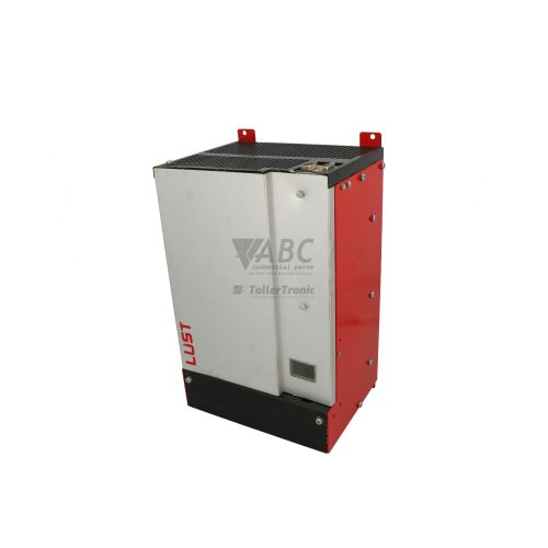
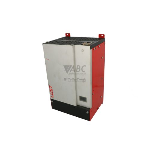
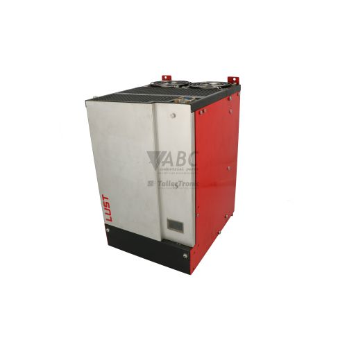
Product photos are for illustration purposes only and may differ from the actual product delivered.
Some of the content on this page was created with the help of AI. While we strive to provide accurate and up-to-date information, errors may occur.