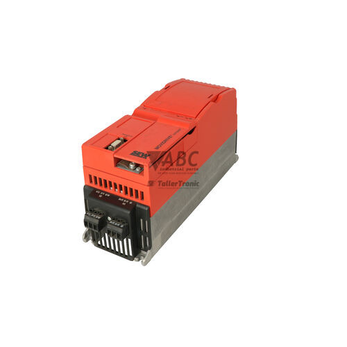
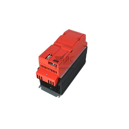
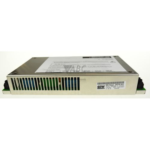
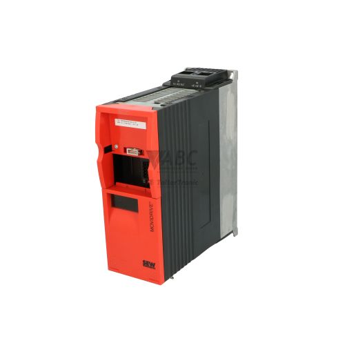
SEW Eurodrive 08268355 MCF41A0015-5A3-4-00 MOVIDRIVE compact A Inverter


Het item werd toegevoegd aan uw offerteaanvraag
Product Information
The SEW Eurodrive 08268355 (Model MCF41A0015-5A3-4-00) is a 1.5 kW frequency inverter from the MOVIDRIVE compact A family, engineered for speed and torque control of 3-phase AC asynchronous motors without requiring encoder feedback. Designed to operate across a mains supply voltage range of 380 V to 500 V AC at 50/60 Hz, this drive provides a continuous output current rating of 4.0 A. Operating performance is driven by flux-oriented Voltage Frequency Control (VFC), providing high torque stability at low speeds. An integrated braking transistor supports dynamic four-quadrant operation when used with an external braking resistor, making the unit well suited for automated conveyor lines, packaging systems, and material handling applications.
Network integration and system communications are facilitated through onboard interfaces, including a PROFIBUS DP fieldbus interface supporting transmission rates up to 12 Mbps, a CAN-based SBus for inter-drive system networking, and an RS-485 serial connection running the MOVILINK protocol. Commissioning a replacement drive requires downloading the application parameter set into the device's non-volatile memory using either a pluggable DBG11B keypad or PC-based MOVITOOLS MotionStudio software via USB11A or UBG11A interface adapters. Replacement units must be configured with matching parameter structures and network addresses prior to operation, with technical support available through ABC Industrial Parts for parameter transfer and pre-commissioning preparation.
Diagnostic monitoring and real-time operational feedback are provided via housing LEDs and the optional keypad 7-segment display. A solid green PROFIBUS RUN LED confirms active fieldbus communication, whereas a solid or flashing red PROFIBUS BUS-FAULT LED indicates loss of communication, incorrect baud rate, or wiring faults. Internal drive diagnostics maintain a non-volatile fault buffer storing the last four error events alongside active system parameters. When facing hardware failure, such as power section damage or control circuit errors, internal components are non-serviceable in the field; sourcing a tested replacement or utilizing repair services via ABC Industrial Parts offers an efficient route to minimizing equipment downtime.
Technical Specifications
| Manufacturer | SEW Eurodrive |
| Part Number | 08268355 |
| Model / Type | MCF41A0015-5A3-4-00 |
| Product Family | MOVIDRIVE compact A |
| Component Type | Frequency Inverter |
| Recommended Motor Power | 1.5 kW |
| Supply Voltage Range | 380 - 500 V AC |
| Supply Frequency | 50/60 Hz |
| Rated Output Current | 4.0 A |
| Control Mode | VFC (Voltage Frequency Control) |
| Operating Quadrants | 4 |
| PWM Switching Frequency | 4 / 8 / 12 / 16 kHz |
| Fieldbus Interface | PROFIBUS DP |
| System Bus Interface | SBus (CAN-based) |
| Serial Interface | RS-485 (MOVILINK) |
Programming and Configuration
Parameterization of the MCF41A0015-5A3-4-00 inverter is executed using the optional pluggable DBG11B programming keypad or PC engineering software via MOVITOOLS MotionStudio. Connection between a PC workstation and the drive is established through the RS-485 serial port utilizing USB11A or UBG11A interface adapters.
The inverter stores dual non-volatile complete parameter sets internally. This parameter architecture allows technicians to maintain redundant operational profiles or save custom motor maps. Using the DBG11B keypad or MOVITOOLS MotionStudio, stored parameter files can be uploaded from an operating drive and written directly to replacement hardware to duplicate operation.
Communication and System Integration
The MCF41A0015-5A3-4-00 incorporates an onboard PROFIBUS DP interface capable of communication speeds up to 12 Mbps. This fieldbus connectivity provides direct integration into centralized PLC network structures, enabling control commands, setpoint adjustments, and cyclic feedback without additional fieldbus option cards.
In addition to PROFIBUS DP, the unit features an integrated CAN-based system bus (SBus) designed for inter-inverter networking and multi-drive coordination. A dedicated RS-485 serial port operating on the SEW MOVILINK protocol provides direct access for diagnostic software monitoring and keypad interaction.
Diagnostics and Status Indication
Operational status and fault conditions are communicated through housing status LEDs, the DBG11B keypad 7-segment display, and online diagnostic software monitors within MOVITOOLS MotionStudio via the RS-485 connection.
The drive maintains an internal diagnostic fault memory buffer that records the last four fault events along with operational system parameters captured at the moment of failure. This buffer allows maintenance technicians to identify recurring issues such as line voltage drops, motor overloads, or fieldbus timeout errors.
Status LED Indicators
| LED | Color/Status | Meaning |
|---|---|---|
| PROFIBUS RUN | Green - Solid | Fieldbus communication active and operating correctly |
| PROFIBUS BUS-FAULT | Red - Solid / Flashing | Fieldbus error: communication interrupted, incorrect baud rate, or bus connection fault |
Replacement and Spare Part Considerations
When commissioning a replacement SEW Eurodrive 08268355 MCF41A0015-5A3-4-00 drive, parameter values must be restored from a backup file or uploaded directly from the original unit via the DBG11B keypad or MOVITOOLS MotionStudio software. Unconfigured replacement units operate on default factory settings and will not properly drive the motor or communicate with the network.
In addition to drive parameter sets, fieldbus settings must be verified manually. Ensure that the PROFIBUS station address, baud rate configurations, and termination resistor switches match the network topography of the replaced drive. Motor connection phases, braking resistor wiring, and thermal sensor connections (TF/TH) should also be inspected prior to restoring main power.
Error Codes & Fault Codes
The following error codes may be displayed during operation or diagnostics:
| Code | Name | Description | Possible Cause | Recommended Action |
|---|---|---|---|---|
| 01 | Overcurrent | Output current limit exceeded due to short circuit, excessive load, or defective power section. | Short circuit at output, motor power too large, motor lead defective, or damaged inverter output stage. | Check motor output wiring for short circuits and ground faults; check motor parameter configuration; if fault persists with disconnected motor, internal output stage is damaged requiring unit replacement/repair. |
| 03 | Ground fault | Earth fault detected at motor output phases. | Ground fault in motor lead cable, ground fault in motor winding, or internal current sensor failure. | Inspect motor cables and test motor insulation resistance. Replace damaged cables or motor if ground fault exists. |
| 04 | Brake chopper | Excessive regenerative current or failure in braking resistor circuit. | Regenerative energy too high, short circuit in braking resistor circuit, or brake chopper defect. | Check braking resistor resistance and connection; check braking resistor cable; replace unit if internal brake chopper transistor is damaged. |
| 06 | Mains phase failure | Phase missing in 3-phase supply mains connection. | Mains voltage phase missing, blown line fuse, unbalance in power grid. | Check supply line voltages and line fuses. |
| 07 | DC link overvoltage | DC link voltage exceeded upper threshold. | Deceleration time too short, braking resistor disconnected or wrong value, excessive regenerative power. | Extend deceleration ramp time, verify braking resistor value and connection, replace braking resistor if open circuit. |
| 08 | DC link undervoltage | DC link voltage dropped below minimum threshold. | Mains voltage interrupted, main contactor dropped out, supply voltage too low. | Check supply voltage level, inspect mains contactor and line fuses. |
| 11 | Overtemperature heatsink | Inverter heatsink thermal threshold exceeded. | Insufficient cooling airflow, ambient temperature too high, fan failure, dirty heatsink. | Clean cooling fins, verify cabinet ventilation and ambient temperature, check heat sink fan operation. |
| 17 | System fault | Internal hardware or processor system fault. | Internal electronic component failure, CPU fault, severe EMC interference. | Internal hardware fault — power cycle unit; if error persists, replace the unit. |
| 18 | System fault | Internal hardware fault on control board. | Internal electronic board failure or corrupt internal memory. | Internal hardware fault — return unit for repair or replace inverter. |
| 19 | System fault | Internal memory or control section fault. | Hardware component error or memory corruption. | Internal hardware fault — unit requires repair or replacement. |
| 25 | EEPROM error | Error accessing internal non-volatile EEPROM memory. | Defective NVRAM/EEPROM memory chip or power failure during parameter write. | Reset parameters to factory defaults and download configuration again. If error recurs, internal board failure — replace unit. |
| 26 | External fault | Fault signal received via programmed digital input. | External fault contact triggered (e.g., motor thermal protection switch, emergency stop). | Troubleshoot external device connected to digital input programmed as 'External Fault'. |
| 27 | Limit switches | Both limit switch inputs actuated simultaneously or incorrect logic state. | Broken limit switch wiring, defective switches, or wrong digital input assignment. | Check limit switch wiring and digital input signals. |
| 28 | Fieldbus timeout | Communication failure on fieldbus interface (PROFIBUS DP). | Bus cable disconnected, master PLC stopped, incorrect PROFIBUS address or bus termination. | Check PROFIBUS cable, termination resistors, master state, and fieldbus address setting. |
| 31 | TF/TH tripping | Motor thermistor (TF) or thermostat (TH) triggered motor protection fault. | Motor thermal overload, cooling fan failure on motor, broken thermistor cable. | Allow motor to cool, check motor load, verify thermistor sensor cable integrity. |
| 37 | System bus timeout | Timeout during SBus system bus communication. | SBus connection interrupted, SBus master inactive, or wrong baud rate. | Check SBus cable connection, terminating resistor, and SBus communication configuration. |
| 43 | RS485 timeout | Timeout on serial RS-485 interface. | Serial cable disconnected, PC/keypad communication interrupted. | Check RS-485 connections and serial master/keypad status. |
| 44 | Inverter utilization / Motor overload | Ixt motor or inverter thermal overload algorithm tripped. | Continuous operation above continuous current rating. | Reduce load, extend acceleration time, verify drive sizing. |
Frequently Asked Questions
What tools are needed to configure the SEW 08268355 inverter?
The drive can be configured using a pluggable DBG11B keypad or MOVITOOLS MotionStudio software connected via a USB11A or UBG11A RS-485 interface adapter.
Does the MCF41A0015-5A3-4-00 drive require an encoder for speed control?
No, the inverter utilizes open-loop VFC (Voltage Frequency Control) to achieve stable torque and speed regulation without encoder feedback.
How are parameters transferred from a failed inverter to a spare unit?
Parameters stored in the non-volatile memory can be backed up using the DBG11B keypad or MOVITOOLS MotionStudio and downloaded directly into the replacement drive.
What communication interfaces are integrated into this unit?
The inverter includes a built-in PROFIBUS DP interface (up to 12 Mbps), a CAN-based SBus system bus, and an RS-485 serial interface running the MOVILINK protocol.
What does a solid or flashing red PROFIBUS BUS-FAULT LED indicate?
It indicates a fieldbus communication fault, such as a disconnected bus cable, incorrect baud rate, wrong station address, or improper bus termination.
Take advantage of our exchange formula
A defective product does not have to be worthless. At ABC Industrial Parts, you can hand in defective products and immediately benefit from a discount on your new purchase. This is a smart way to save money while contributing to a circular economy.
Play it safe with our warranty conditions
Industrial plants prefer to keep running invariably, no matter what. Therefore, it is essential that you can rely on high-quality products and/or sustainable repairs. With our warranty conditions, you can count on certainty, whether you choose new, used or repaired products.
Data backup and recovery
Have you lost valuable parameters or data due to a malfunction while the manufacturer no longer provides support? At ABC Industrial Parts, we help you secure this data, both for common and specific products.
Specific firmware and hardware versions
If you are working with specific hardware or firmware versions that are no longer available from the manufacturer, ABC Industrial Parts is your partner. When making your enquiry, clearly state which versions you need, we will then look at the possibilities of supplying those versions, so that your installations continue to function optimally.
Disclaimer:
We are not an authorised distributor of SEW Eurodrive.
Product photos are for illustration purposes only and may differ from the actual product delivered.
Some of the content on this page was created with the help of AI. While we strive to provide accurate and up-to-date information, errors may occur.