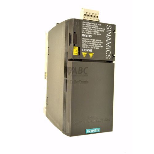
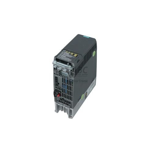
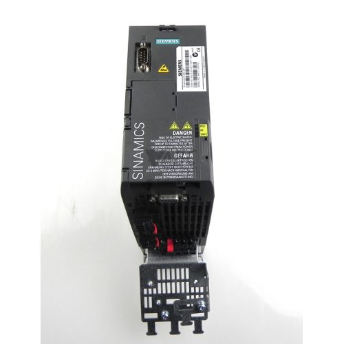
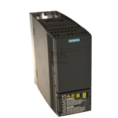
Siemens 6SL3210-1KE18-8AF1 SINAMICS G120C Inverter 4kW


Het item werd toegevoegd aan uw offerteaanvraag
Product Information
The Siemens 6SL3210-1KE18-8AF1 is a compact SINAMICS G120C variable frequency inverter designed for continuous motor speed control and dynamic torque regulation in automated industrial applications. Operating across a 3-phase line supply range of 380 V AC to 480 V AC at 47 to 63 Hz, this Frame Size FSB unit provides power ratings of 4.0 kW with an 8.8 A output current for low overload duties, and 3.0 kW with a 7.3 A output current for high overload conditions. Housed in an IP20 enclosure, the drive includes an integrated Class A EMC line filter for suppression of electromagnetic interference alongside built-in Safe Torque Off (STO) functional safety certified to SIL 2 and PL d compliance.
Network integration is provided by an integrated dual-port RJ45 multi-protocol interface supporting both PROFINET IO and EtherNet/IP, enabling direct line or ring topologies connected to SIMATIC S7-1200 or S7-1500 controllers. Physical interface options comprise six digital inputs, one relay output, one transistor output, one analog input, and one analog output. Installing a replacement unit requires restoring drive parameters, motor data, and safety configurations via TIA Portal V13 or higher using SINAMICS Startdrive, standalone STARTER software, or attached IOP-2 or BOP-2 operator panels. Rapid parameter cloning is also supported through a SINAMICS SD memory card or front mini-USB port. ABC Industrial Parts can assist maintenance teams in sourcing and preparing spare units to minimize system downtime during replacements.
Real-time diagnostic feedback is provided by front-panel LEDs including RDY for drive operational status, BF for bus fault indication, LNK1 and LNK2 for Ethernet port communication links, and SAFE for STO safety status. Detailed diagnostic data and history can be queried via parameter p0945 for active faults, p2110 for alarms, and p0947 for fault history logs. Initial troubleshooting should involve verifying incoming 3-phase mains voltage, examining motor cable connections, and evaluating safety circuit wiring. When internal hardware errors or NVRAM faults occur that cannot be resolved through power cycles or parameter resets, sourcing a tested exchange drive or unit repair through ABC Industrial Parts offers a fast path back to operational availability.
Technical Specifications
| Manufacturer | Siemens |
| Part Number | 6SL3210-1KE18-8AF1 |
| Model / Type | SINAMICS G120C |
| Product Family | SINAMICS |
| Component Type | Frequency Inverter |
| Rated Power (Low Overload) | 4 kW |
| Rated Power (High Overload) | 3 kW |
| Output Current (Low Overload) | 8.8 A |
| Output Current (High Overload) | 7.3 A |
| Supply Voltage Range | 380 - 480 V AC |
| Line Frequency Range | 47 - 63 Hz |
| Output Frequency Range | 0 - 550 Hz |
| Frame Size | FSB |
| EMC Filter Class | Class A |
| Digital Inputs | 6 |
| Digital Outputs | 2 |
| Analog Inputs | 1 |
| Analog Outputs | 1 |
| Integrated Safety | Safe Torque Off (STO) |
| IP Rating | IP20 |
Programming and Configuration
Engineering and commissioning of the Siemens 6SL3210-1KE18-8AF1 variable frequency drive are conducted within the Siemens TIA Portal framework using SINAMICS Startdrive software (V13 or higher) or the standalone STARTER software tool. These software tools enable full parameterization of motor data, control curves including V/f and sensorless vector control (SLVC), acceleration/deceleration ramps, and safety parameters.
For rapid parameter transfer without a PC connection, the drive supports memory cloning using a SINAMICS SD memory card (6SL3054-4AG00-2AA0) inserted into the card slot, or direct PC access through the integrated front mini-USB connection. Optional BOP-2 (Basic Operator Panel) and IOP-2 (Intelligent Operator Panel) units can be attached directly to the drive front to adjust parameters, perform manual test runs, and monitor operational status.
Communication and System Integration
The 6SL3210-1KE18-8AF1 drive features an integrated dual-port RJ45 interface supporting PROFINET IO and EtherNet/IP multi-protocol industrial communication. This dual-port layout permits direct cabling in line and ring network topologies without requiring extra external communication modules or network switches.
The inverter integrates directly into Siemens automation environments with seamless cyclic and acyclic communication to SIMATIC S7-1200 and S7-1500 controllers. Hardwired I/O integration is provided through six digital inputs, one relay output, one transistor output, and selectable analog input and output channels.
Diagnostics and Status Indication
Visual operational feedback is provided via four status LEDs on the drive front cover. The RDY LED displays overall drive status and operating modes, the BF LED indicates fieldbus network connection health, the LNK1 and LNK2 LEDs indicate physical connection and data activity on the Ethernet ports, and the SAFE LED shows the active state of the Safe Torque Off safety function.
Detailed diagnostics are recorded internally in dedicated parameter buffers. Parameter p0945 stores the active fault code log, parameter p2110 retains active alarm codes, and parameter p0947 maintains fault history events. Diagnostics can be accessed and analyzed through TIA Portal, STARTER software, or connected BOP-2 and IOP-2 operator displays.
Status LED Indicators
| LED | Color/Status | Meaning |
|---|---|---|
| RDY | Green/Red - Solid/Flashing | Solid Green: Ready/Running; Flashing Green: Commissioning/Ramp-up; Solid Red: Drive fault; Flashing Red: Internal hardware/firmware fault |
| BF | Red - Solid/Flashing/Off | Off: Fieldbus normal; Solid Red: Bus fault or physical link loss; Flashing Red: Bus address assignment fault or timeout |
| LNK1 / LNK2 | Green - Solid/Flashing/Off | Solid Green: Physical link established on Port 1/2; Flashing Green: Active data transmission; Off: No physical link |
| SAFE | Yellow - Solid/Flashing/Off | Solid Yellow: STO safety function active; Flashing Yellow: Safety error or mandatory testing timer elapsed; Off: Safety function inactive |
Replacement and Spare Part Considerations
When selecting a replacement for a Siemens 6SL3210-1KE18-8AF1 inverter, confirm that the target unit matches Frame Size FSB dimensions, 380-480 V AC 3-phase power ratings, and the integrated Class A EMC filter specification. Ensure that application continuous current demands fit within 8.8 A (Low Overload) or 7.3 A (High Overload) operational profiles.
A replacement drive must be commissioned with the exact parameter set from the original unit. Parameter restoration can be performed using a SINAMICS SD memory card, mini-USB download, or software project transfer via SINAMICS Startdrive or STARTER. Certain configuration updates, including firmware revisions, mandate a complete 24 V DC control power and main line voltage power cycle (F01018) before the drive becomes active.
In the event of non-volatile EEPROM failure (F03001) or internal monitoring channel mismatch (F01611), software reset commands (p0970=1) will not clear the condition. Hardware faults on internal control circuit boards or power modules require exchanging the complete drive assembly or sending the unit for specialist repair.
Error Codes & Fault Codes
The following error codes may be displayed during operation or diagnostics:
| Code | Name | Description | Possible Cause | Recommended Action |
|---|---|---|---|---|
| F01000 | Software fault internal | An internal software condition or memory access fault occurred in the control unit. | Firmware error, invalid parameter combination, or internal board memory fault. | Perform power cycle. If fault persists, update firmware or replace Control Unit/Inverter board. |
| F01001 | Floating point exception | An illegal floating point math operation occurred during internal calculations. | Internal firmware operation fault or corrupted parameter RAM memory. | Power cycle drive. Restore factory default parameters (p0970=1) and re-commission. Replace unit if fault recurs. |
| F01015 | Software error internal | Internal program execution monitoring triggered a fault response. | Internal execution task timeout or hardware logic fault. | Power cycle unit. Update firmware to latest release or replace drive unit. |
| F01018 | POWER ON restart request | A drive parameter change or update was made that requires a complete 24V/power restart. | Firmware update or change to core parameters requiring power restart. | Turn off 24V supply and line voltage, wait for unit to discharge, then re-apply power. |
| F01600 | STOP A Triggered | Safety Integrated STOP A was initiated due to a detected safety monitoring fault. | Safety input channel mismatch, STO wiring fault, or internal safety hardware circuit error. | Check STO terminal wiring, dual-channel inputs, and safety commissioning parameters. Perform safety reset. |
| F01611 | Defect in a monitoring channel | Safety Integrated fault in cross-wise comparison between internal monitoring channels. | Internal safety processor mismatch or hardware defect in safety switch circuits. | Check safety wiring and parameters. If fault persists on power cycle, internal safety hardware fault - unit requires repair/replacement. |
| F03001 | NVRAM fault | Failure detected when reading or writing internal non-volatile EEPROM memory. | Defective internal NVRAM/EEPROM chip or power interruption during write process. | Power cycle unit and reload factory setting (p0970=1). If NVRAM fault persists, unit has board-level hardware failure and must be replaced. |
| F07011 | Motor overtemperature | Motor temperature exceeds configured fault limit or temperature sensor triggered. | Motor overload, insufficient cooling, defective motor temperature sensor (PTC/KTY/PT1000), or incorrect parameter settings (p0604/p0605). | Check motor loading and cooling fan function. Verify temperature sensor connection and motor thermal model parameters. |
| F07400 | Maximum speed exceeded | Actual motor speed exceeded maximum configured threshold (p1082). | Incorrect speed controller tuning, driving load overhauling motor, or wrong pulse encoder settings. | Check speed limit p1082, dynamic load torque, and ramp-down configuration. |
| F07801 | Motor overcurrent | Output current to motor exceeded maximum current threshold. | Motor cable short circuit, ground fault, motor winding short, ramp times too short, motor mechanical lock/stall. | Inspect motor cables and motor insulation. Check mechanical load for binding. Increase acceleration time (p1120). |
| F07802 | Motor stalled | Drive detected motor stall condition under load. | Excessive load torque, mechanical blockage, torque limit set too low, voltage/current limit reached. | Check motor load and mechanical brake operation. Verify torque limits (p1520/p1521) and current limits (p0640). |
| F07900 | Motor blocked | Motor is operating at current limit and zero speed longer than stall time setting (p2177). | Mechanical stall, frozen shaft, mechanical brake not releasing. | Check load mechanics, check mechanical holding brake release circuit. |
| F30001 | Power unit: Overcurrent | Inverter output stage peak current limit exceeded. | Short circuit at inverter output terminals, ground fault in motor cable, incorrect motor data entry, loose motor lead connection. | Check motor wiring with megohmmeter. Verify motor nameplate parameter setup (p0300..p0311). Check for damaged IGBT module. |
| F30002 | Power unit: DC link overvoltage | DC link bus voltage exceeded upper shutdown threshold. | Line supply voltage too high, regenerative load energy during deceleration without braking resistor, deceleration ramp time (p1121) too short. | Increase deceleration time p1121, enable DC link voltage controller (p1240), or install optional braking resistor. |
| F30003 | Power unit: DC link undervoltage | DC link voltage fell below minimum allowable operating threshold. | Line power supply interruption, phase loss, severe line voltage drop, or defective pre-charging relay. | Measure 3-phase AC input voltage under load. Inspect mains fuses, contactors, and line supply stability. |
| F30004 | Power unit: Overtemperature heat sink | Heatsink temperature exceeded internal trip threshold. | Cooling fan defective or stopped, clogged heatsink air channels, ambient temperature too high, pulse frequency set too high. | Inspect cooling fan operation, clean heatsink fins, ensure adequate cabinet ventilation and clearance distances. |
| F30005 | Power unit: Overload I2t | Inverter power section I2t thermal load counter exceeded limit. | Continuous overload operating cycle beyond drive continuous current rating. | Check load duty cycle against drive rating (LO vs HO mode). Reduce mechanical load or duty cycle. |
| F30011 | Power unit: Line phase failure | One phase of the 3-phase AC supply voltage is missing or severely unbalanced. | Blown main fuse, open phase on main contactor, bad power wire termination at L1/L2/L3. | Measure input voltage across L1-L2, L2-L3, L1-L3 under load. Check incoming supply fuses and contactor contacts. |
| F30015 | Power unit: Phase failure motor | Phase interruption in motor output terminals (U, V, W). | Disconnected motor cable, open contactor in motor line, unbalanced motor winding resistance. | Check output terminal connections U, V, W and motor terminal box connections. Check motor winding resistance with ohmmeter. |
| F30027 | Power unit: Precharging DC link time monitoring | DC link bus failed to reach pre-charge voltage within allowable timeframe. | AC input supply voltage too low, line phase missing, short circuit in DC link, or damaged pre-charge resistor/relay. | Verify line input voltage. Inspect drive DC link terminals for short circuits. If input voltage is normal, internal pre-charge circuit hardware failure. |
| F30036 | Power unit: Overtemperature heat sink internal | Internal temperature sensor on power stage registered excessive temperature. | Fan failure, blocked airflow, heavy overload at low output speeds. | Check fan functioning, ambient air flow, and clean heatsink structure. |
| F30040 | Power unit: Undervoltage 24 V | Internal or external 24V DC control voltage supply dropped below threshold. | External 24V supply overloaded, excessive current drawn by I/O terminals, or internal 24V rail fault. | Check external 24V DC auxiliary power supply voltage and wire loading. |
Frequently Asked Questions
How do I back up and restore parameters on the 6SL3210-1KE18-8AF1?
Parameter sets can be saved and restored using a SINAMICS SD memory card (6SL3054-4AG00-2AA0), connected to a PC via the front mini-USB port using SINAMICS Startdrive or STARTER software, or managed through an attached BOP-2 or IOP-2 operator panel.
Which communication protocols are built into this drive?
The drive includes an integrated dual-port RJ45 interface that supports both PROFINET IO and EtherNet/IP protocols, allowing direct connection into line or ring automation topologies.
What power ratings does the 6SL3210-1KE18-8AF1 support?
The unit is rated at 4.0 kW (8.8 A output current) for Low Overload applications and 3.0 kW (7.3 A output current) for High Overload applications, operating on a 3-phase input supply of 380 V AC to 480 V AC.
What does a solid red RDY LED indicate on the drive cover?
A solid red RDY LED indicates an active drive fault. Active fault codes can be read via parameter p0945, through an attached BOP-2/IOP-2 panel, or within the software diagnostic buffer.
How is integrated functional safety enabled on this drive?
Functional safety is provided via built-in Safe Torque Off (STO), certified to SIL 2 and PL d compliance. STO safely prevents torque-generating energy from reaching the motor without needing external output contactors.
Take advantage of our exchange formula
A defective product does not have to be worthless. At ABC Industrial Parts, you can hand in defective products and immediately benefit from a discount on your new purchase. This is a smart way to save money while contributing to a circular economy.
Play it safe with our warranty conditions
Industrial plants prefer to keep running invariably, no matter what. Therefore, it is essential that you can rely on high-quality products and/or sustainable repairs. With our warranty conditions, you can count on certainty, whether you choose new, used or repaired products.
Data backup and recovery
Have you lost valuable parameters or data due to a malfunction while the manufacturer no longer provides support? At ABC Industrial Parts, we help you secure this data, both for common and specific products.
Specific firmware and hardware versions
If you are working with specific hardware or firmware versions that are no longer available from the manufacturer, ABC Industrial Parts is your partner. When making your enquiry, clearly state which versions you need, we will then look at the possibilities of supplying those versions, so that your installations continue to function optimally.
Disclaimer:
We are not an authorised distributor of Siemens.
Product photos are for illustration purposes only and may differ from the actual product delivered.
Some of the content on this page was created with the help of AI. While we strive to provide accurate and up-to-date information, errors may occur.