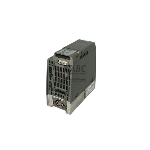
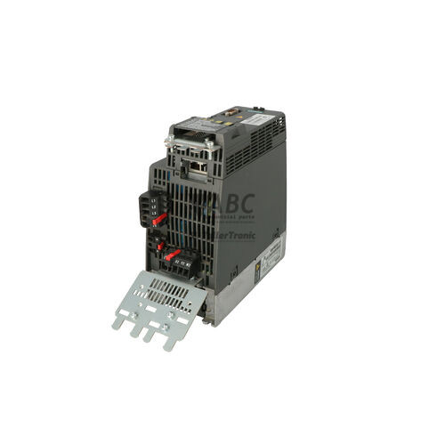
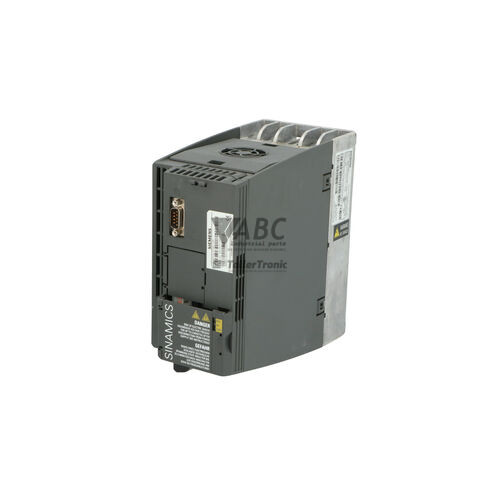
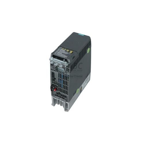
Siemens 6SL3210-1KE21-7AF1 SINAMICS G120C Frequency Inverter


Het item werd toegevoegd aan uw offerteaanvraag
Product Information
The Siemens 6SL3210-1KE21-7AF1 is a compact frequency inverter from the SINAMICS G120C series, designed for controlled speed regulation of three-phase AC induction motors. Operating on a 380 V to 480 V AC supply, this unit features a compact FSB frame size with an integrated Class A EMC line filter to minimize electromagnetic interference in industrial power networks. The drive supports dual load ratings, providing 7.5 kW with 16.5 A continuous output current under Low Overload conditions and 5.5 kW with 12.5 A continuous output current under High Overload demands. Motor control choices include linear V/f, quadratic V/f, and Sensorless Vector Control (SLVC) across an output frequency range of 0 Hz to 550 Hz.
Network integration is established through built-in dual-port RJ45 connectors supporting PROFINET IO and EtherNet/IP protocols for linear or ring network layouts. Control wiring connects via 6 programmable digital inputs, 2 digital outputs, 2 analog inputs, and 1 analog output, alongside hardwired Safe Torque Off (STO) safety terminals conforming to SIL 2 and PL d standards. When commissioning a spare unit, drive parameters must be transferred using a SINAMICS SD card (6SL3054-4AG00-0AA0), operator panels such as the IOP-2 or BOP-2, or engineering software including SINAMICS Startdrive in TIA Portal V13 or higher. Correct alignment of motor data parameters p0300 to p0335 and maximum speed threshold p1082 ensures safe commissioning, while ABC Industrial Parts can support technical teams with spare units and parameter transfer solutions to reduce downtime.
System diagnostic state is displayed through onboard status LEDs (RDY, BF, SAFE), display keypads, parameter buffers r0945 and r0947, or an optional web server interface via the SINAMICS G120 Smart Access Module. First-line troubleshooting involves checking incoming 3-phase line power, motor winding insulation, line fuses, fieldbus cabling, and STO safety circuit input signals. Internal CPU, software, or memory errors such as codes F01000 or F01001 represent non-field-serviceable control board faults. In such events, installing a replacement drive or sending the malfunctioning unit for professional repair through ABC Industrial Parts provides a direct solution to restore machine operation.
Technical Specifications
| Manufacturer | Siemens |
| Part Number | 6SL3210-1KE21-7AF1 |
| Model / Type | SINAMICS G120C |
| Product Family | SINAMICS |
| Component Type | Frequency Inverter |
| Frame Size | FSB |
| Supply Voltage Range | 380 - 480 V AC |
| Rated Power (Low Overload) | 7.5 kW |
| Rated Power (High Overload) | 5.5 kW |
| Continuous Output Current (Low Overload) | 16.5 A |
| Continuous Output Current (High Overload) | 12.5 A |
| Output Frequency Range | 0 - 550 Hz |
| Pulse / Switching Frequency | 4 kHz |
| Integrated EMC Filter | Class A |
| Integrated Safety Function | Safe Torque Off (STO) SIL 2 / PL d |
| Supported Fieldbus Protocols | PROFINET IO / EtherNet/IP |
| Digital Inputs | 6 |
| Digital Outputs | 2 |
| Analog Inputs | 2 |
| Analog Outputs | 1 |
Programming and Configuration
Engineering and commissioning of the SINAMICS G120C 6SL3210-1KE21-7AF1 frequency inverter are executed using SINAMICS Startdrive software embedded in TIA Portal (V13 or higher) or via the STARTER configuration tool. Communication with the software tools takes place over the onboard Mini-USB port or directly through the dual-port PROFINET connection. Programming involves configuring motor equivalent circuit parameters p0300 to p0335, setting maximum output speed in p1082, and selecting linear, quadratic, or Sensorless Vector Control (SLVC) operation.
For manual onsite operation, parameter adjustment, and drive status checks, the unit accommodates plug-in operator panels including the IOP-2 and BOP-2. Configuration cloning between drives can be performed using an optional SINAMICS SD card (6SL3054-4AG00-0AA0). Inserting the SD card into the onboard slot allows full parameter sets to be uploaded, stored, and flashed onto a replacement drive without requiring a PC connection.
Communication and System Integration
The 6SL3210-1KE21-7AF1 drive includes an integrated dual-port Ethernet interface supporting PROFINET IO and EtherNet/IP industrial protocols. The built-in RJ45 dual ports facilitate line and ring network topologies directly between drives and central PLC controllers, such as SIMATIC S7-1200 and S7-1500 systems, without needing extra fieldbus switches.
In addition to cyclic communication for setpoint transfer and status signals, the drive supports acyclic PROFINET channel diagnostics. System operators can also configure and diagnose the inverter wirelessly via a web browser when using the optional SINAMICS G120 Smart Access Module attachment.
Diagnostics and Status Indication
The inverter delivers diagnostic data through physical status LEDs, diagnostic parameters, and error display text on IOP-2 or BOP-2 keypads. Diagnostic parameters r0945 and r0947 record fault code history, while parameters r2122 and r2123 detail the alarm buffer. Diagnostic information is accessible via TIA Portal Startdrive, STARTER, or through cyclic fieldbus diagnostic messaging.
Status LED Indicators
| LED | Color/Status | Meaning |
|---|---|---|
| RDY | Green / Red - Solid / Flashing | Green: drive ready to operate; Flashing Green: commissioning / parameter initialization; Red: drive fault present; Flashing Red: internal hardware/firmware fault requiring service or restart. |
| BF | Red - Off / Solid / Flashing | Off: fieldbus communication operational; Flashing Red: bus error / communication setpoint fault; Solid Red: no communication connection to fieldbus master. |
| SAFE | Yellow - Solid / Flashing | Yellow: Safe Torque Off (STO) safety function active; Flashing Yellow: STO safety fault present. |
Replacement and Spare Part Considerations
When swapping a damaged unit with a replacement 6SL3210-1KE21-7AF1 drive, dimensional and mechanical compatibility is ensured by the standard FSB frame size. The presence of the built-in Class A EMC filter eliminates the need to install external line filtering components in the cabinet layout.
A replacement drive will not run immediately upon physical installation without transferring parameter settings. Parameter sets should be restored using a SINAMICS SD card transferred from the original unit or downloaded from a backup project using TIA Portal Startdrive or STARTER software via the Mini-USB port or PROFINET. Ensure fieldbus IP addresses, STO safety parameters, and motor equivalent circuit data match the machine setup.
Error Codes & Fault Codes
The following error codes may be displayed during operation or diagnostics:
| Code | Name | Description | Possible Cause | Recommended Action |
|---|---|---|---|---|
| F01000 | Internal software error | An internal software error has occurred in the Control Unit. | Firmware error or unrecoverable instruction exception. | Perform POWER ON (power cycle). If fault persists, update firmware or replace the drive unit — internal control board failure. |
| F01001 | Floating Point Exception | An internal floating point operation error occurred in the processor. | Internal CPU compute error. | Power cycle the drive. Internal processor fault — return unit for repair if persistent. |
| F01600 | STOP A Triggered | Safety Integrated: STOP A was initiated by the safety function. | Safety fault or STO requested by safety controller / digital inputs. | Acknowledge fault, reset safety input condition, check safety circuit wiring. |
| F030001 | Power unit: Overcurrent | Inverter output current limit exceeded. | Short circuit or ground fault at inverter output, acceleration time too short, motor oversized or jammed. | Check motor cable and winding insulation, increase acceleration ramp time, check motor load. |
| F030002 | Power unit: DC link overvoltage | DC link voltage exceeded upper threshold limit. | Line supply voltage too high, regenerative energy from motor during deceleration without braking chopper/resistor. | Check supply voltage level, extend deceleration ramp time, check integrated braking chopper and external braking resistor. |
| F030003 | Power unit: DC link undervoltage | DC link voltage dropped below lower threshold limit. | Main power supply failure, supply voltage drop or line phase failure. | Check mains power supply voltage and incoming line fuses. |
| F030004 | Drive inverter: Overtemperature heatsink | Heatsink temperature exceeded permissible threshold limit. | Inadequate cooling air flow, fan failure, ambient temperature too high, continuous overload. | Check cabinet fan and heat sink cooling fins for blockage, reduce switching frequency or load. |
| F030005 | Power unit: I2t overload | Inverter thermal load exceeded limit. | Continuous overload duty cycle exceeded capacity of inverter power section. | Reduce duty cycle / load current or size inverter up. |
| F030011 | Line phase failure | One phase of the 3-phase incoming AC supply missing. | Blown input fuse, loose wire terminal connection, unbalance in grid line. | Check line supply fuses, incoming line terminals, and line supply balance. |
| F030015 | Phase failure motor | One motor phase disconnected. | Interrupted motor cable, motor contactor opened during run, bad motor terminal connection. | Check motor connections, motor cable integrity, and output contactor wiring. |
| F030021 | Ground fault | Ground fault detected on motor connection. | Insulation breakdown in motor winding or motor cable to ground. | Measure motor winding insulation resistance and check motor cable for earth breakdown. |
| F07011 | Motor overtemperature | Motor thermal model or PTC/KTY sensor indicates motor overtemperature. | Motor overload, insufficient motor cooling at low speeds, defective temperature sensor. | Check motor load, motor fan, and motor temperature sensor connection. |
| F07801 | Motor blocked | Motor has stalled / mechanical block. | Mechanical obstruction in driven machine, torque limit set too low. | Check driven machine mechanism for mechanical blockages or jammed load. |
| F07900 | Drive: Motor blocked | Motor is operating at current limit and zero speed. | Mechanical lock on motor shaft. | Check motor load and mechanical brake opening. |
| F07901 | Motor overspeed | Motor speed exceeded maximum speed threshold. | Incorrect speed controller parameters, load driving the motor faster than setpoint. | Check speed limits p1082 and motor encoder / control parameters. |
| F07902 | Motor stalled | Motor slipped out of synchronism / stalled under vector control. | Load too high, improper motor equivalent circuit parameters. | Perform motor identification run, check motor data p0300-p0335. |
| F08501 | PN/COMM: Setpoint timeout | Fieldbus communication setpoint transmission interrupted. | Broken PROFINET cable, PLC controller stopped or powered off, network fault. | Check PROFINET cable connectors, network topology, and PLC run state. |
Frequently Asked Questions
How do I transfer parameter settings to a replacement 6SL3210-1KE21-7AF1 drive?
Parameter settings can be cloned by inserting a SINAMICS SD card (6SL3054-4AG00-0AA0) into the replacement drive, transferring the backup via TIA Portal Startdrive or STARTER software over Mini-USB/PROFINET, or using an IOP-2 or BOP-2 operator panel.
What does a flashing red RDY LED indicate on this SINAMICS G120C drive?
A flashing red RDY LED indicates an unrecoverable internal hardware or firmware fault. If power cycling the drive does not clear the error, the unit requires firmware updating, repair, or replacement.
What power ratings does the 6SL3210-1KE21-7AF1 inverter support?
The drive supports dual ratings: 7.5 kW with 16.5 A output current for Low Overload (LO) duty, and 5.5 kW with 12.5 A output current for High Overload (HO) duty.
Does the 6SL3210-1KE21-7AF1 feature integrated safety functions?
Yes, the inverter includes integrated Safe Torque Off (STO) functional safety, certified to SIL 2 according to EN 61508 and PL d according to EN ISO 13849-1.
What causes fault code F030001 and how can it be resolved?
Fault code F030001 indicates power unit overcurrent, caused by a motor output short circuit, ground fault, jammed load, or too rapid acceleration. Resolution involves measuring motor insulation, checking driven machinery for mechanical locks, and increasing ramp acceleration time.
Take advantage of our exchange formula
A defective product does not have to be worthless. At ABC Industrial Parts, you can hand in defective products and immediately benefit from a discount on your new purchase. This is a smart way to save money while contributing to a circular economy.
Play it safe with our warranty conditions
Industrial plants prefer to keep running invariably, no matter what. Therefore, it is essential that you can rely on high-quality products and/or sustainable repairs. With our warranty conditions, you can count on certainty, whether you choose new, used or repaired products.
Data backup and recovery
Have you lost valuable parameters or data due to a malfunction while the manufacturer no longer provides support? At ABC Industrial Parts, we help you secure this data, both for common and specific products.
Specific firmware and hardware versions
If you are working with specific hardware or firmware versions that are no longer available from the manufacturer, ABC Industrial Parts is your partner. When making your enquiry, clearly state which versions you need, we will then look at the possibilities of supplying those versions, so that your installations continue to function optimally.
Disclaimer:
We are not an authorised distributor of Siemens.
Product photos are for illustration purposes only and may differ from the actual product delivered.
Some of the content on this page was created with the help of AI. While we strive to provide accurate and up-to-date information, errors may occur.