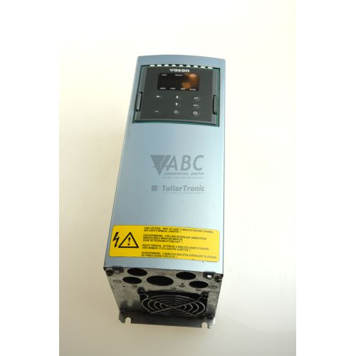
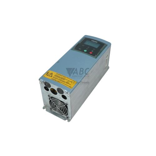
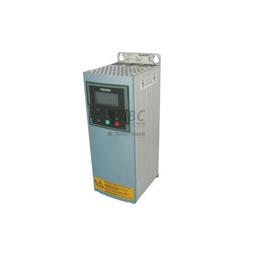
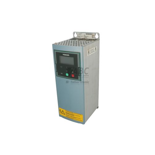
Vacon NXP00725A5H1SSSANA3000000 NXP0072 5 A AC Frequency Inverter



Het item werd toegevoegd aan uw offerteaanvraag
Product Information
The Vacon NXP00725A5H1SSSANA3000000 is an air-cooled AC frequency inverter from the Vacon NXP series designed for high-performance industrial motor control. Built in an FR7 frame size with an IP21 wall-mounted enclosure, this unit operates across a 380 V AC to 500 V AC three-phase supply voltage range. It provides dual power ratings, delivering up to 37 kW with a 72 A rated current under low overload conditions, or 30 kW with a 61 A rated current for high overload applications at 400 V AC. Featuring an integrated AC choke and built-in brake chopper, the drive supports open-loop V/Hz control, sensorless vector control, and full closed-loop vector control up to a maximum output frequency of 320 Hz across demanding heavy-duty operations.
Interfacing the drive with machinery relies on its 5-slot expansion card architecture. This specific model includes three factory-installed boards: the OPTA1 standard I/O card providing 6 digital inputs, 2 analog inputs, 1 digital output, 1 analog output, and 2 relay outputs; the OPTCA card in Slot C for high-speed CANopen DS301 fieldbus networking; and the OPTD3 encoder feedback card for HTL or TTL incremental encoder speed feedback. Commissioning a replacement unit requires matching these expansion board positions and copying the application parameters. Drive parameters can be saved to and restored from the removable graphic display keypad, which holds up to five parameter backup sets, or managed through Vacon NCDrive diagnostic and commissioning software. ABC Industrial Parts can assist maintenance teams with pre-configured replacement units and parameter transfers to minimize machine downtime during drive replacement.
Operational monitoring and troubleshooting are supported through direct diagnostic tools built into the unit. Front status LEDs indicate POWER, RUN, READY, FAULT, and ALARM states, giving technicians immediate visual cues on drive status. Detailed fault diagnosis is accessible via the graphic display keypad, which maintains a fault history menu storing the 30 latest fault records alongside operating parameters at the time of the trip. Initial field checks should cover incoming mains supply phase balance, motor winding insulation resistance, fieldbus cabling, and option card seating. When recurring internal hardware errors or pre-charge circuit failures occur, internal component-level repair or a tested exchange unit from ABC Industrial Parts provides a safe and rapid return to production.
Technical Specifications
| Manufacturer | Vacon |
| Part Number | NXP00725A5H1SSSANA3000000 |
| Model / Type | NXP0072 5 A |
| Component Type | AC Frequency Inverter |
| Product Family | Vacon NXP |
| Supply Voltage Range | 380 - 500 V AC |
| Supply Phases | 3 |
| Rated Power (Low Overload) | 37 kW |
| Rated Power (High Overload) | 30 kW |
| Rated Current (Low Overload) | 72 A |
| Rated Current (High Overload) | 61 A |
| Maximum Output Frequency | 320 Hz |
| Frame Size | FR7 |
| Enclosure Rating | IP21 |
| Digital Inputs | 6 |
| Digital Outputs | 1 |
| Analog Inputs | 2 |
| Analog Outputs | 1 |
| Relay Outputs | 2 |
Programming and Configuration
Configuring the Vacon NXP00725A5H1SSSANA3000000 inverter is managed through the removable graphic display keypad or using the dedicated Vacon NCDrive commissioning software. The graphic keypad features a multi-line display that provides direct access to parameter trees, operating values, and diagnostic logs. Up to five complete parameter sets can be saved directly into the keypad memory, allowing engineers to store baseline operational setups and rapidly transfer parameter configurations to donor or spare drives without requiring a PC connection on the factory floor.
For advanced system setup, trend logging, and drive tuning, the Vacon NCDrive software suite connects directly to the control unit. Through NCDrive, engineers can monitor live operating values such as DC link voltage, motor current, output frequency, and heatsink temperature in real time. The software allows offline project creation, parameter file comparison, and live trend recording during commissioning or dynamic load testing, ensuring precise tuning for closed-loop vector motor control.
Communication and System Integration
System integration for the Vacon NXP00725A5H1SSSANA3000000 drive is driven by its internal 5-slot option architecture. Slot C is fitted with the OPTCA option card, establishing high-speed communication across CANopen DS301 fieldbus networks. This interface allows a master PLC to issue control commands, setpoint frequencies, and operational state requests while receiving real-time diagnostic feedback and parameter values directly over the bus network.
Local control signals and speed feedback are wired through dedicated option cards installed in the drive slots. The OPTA1 basic I/O board handles discrete and analog signals via 6 digital inputs, 2 analog inputs, 1 digital output, 1 analog output, and 2 relay output terminals. Precision closed-loop speed control and dynamic torque positioning are enabled by the OPTD3 encoder interface board, which processes signals from HTL or TTL incremental speed encoders installed on the motor shaft.
Diagnostics and Status Indication
The Vacon NXP00725A5H1SSSANA3000000 frequency inverter features comprehensive status and fault indication tools designed for real-time diagnostics. Five status LEDs on the unit offer immediate clear visual indication: POWER lights green when internal DC control power is live, RUN lights green during output voltage delivery, READY lights green when initialized without active faults, FAULT illuminates red (solid or flashing) when a drive or motor trip occurs, and ALARM shows yellow/orange when a warning condition such as overtemperature or current limit is active.
For deeper diagnostic analysis, the graphic display keypad provides a dedicated Fault History Menu that stores the 30 most recent fault records. Each entry logs the fault code, timestamp, and real-time operational parameters recorded at the moment of failure, including DC link voltage, motor current, output frequency, and heatsink temperature. Additionally, live trend monitoring and diagnostic fault extraction can be conducted through Vacon NCDrive software.
Status LED Indicators
| LED | Color/Status | Meaning |
|---|---|---|
| POWER | Green - Solid | Lit when control unit DC power supply is active and operational. |
| RUN | Green - Solid | Lit when drive is in RUN state and output voltage is enabled. |
| READY | Green - Solid | Lit when drive is powered, initialized, and ready to receive a RUN command without active faults. |
| FAULT | Red - Solid or Flashing | Blinking or continuous lit indicates active fault condition. May indicate motor fault, supply fault, or internal control/power board failure requiring service. |
| ALARM | Yellow / Orange - Solid | Indicates active warning condition (e.g. drive overtemperature warning or current limit reached) without tripping drive output. |
Replacement and Spare Part Considerations
When swapping a failed Vacon NXP drive with a spare NXP00725A5H1SSSANA3000000 unit, physical and electrical ratings must be verified before applying power. The spare must match the 380–500 V AC 3-phase supply input and FR7 frame dimensions. Crucially, the expansion card layout across the 5 internal slots must match the original drive configuration: Slot A requires the OPTA1 basic I/O card, Slot C requires the OPTCA CANopen fieldbus board, and the designated option slot must house the OPTD3 HTL/TTL encoder interface card.
Before putting a replacement drive into service, operational parameters must be restored. Parameter sets saved on the graphic display keypad can be downloaded directly into the new drive's control memory, or parameter files can be loaded via Vacon NCDrive software. Following parameter download, technicians should verify encoder feedback signals, check CANopen node address settings, and perform phase supervision checks prior to running the motor under full load.
Error Codes & Fault Codes
The following error codes may be displayed during operation or diagnostics:
| Code | Name | Description | Possible Cause | Recommended Action |
|---|---|---|---|---|
| F1 | Overcurrent | Drive hardware trip: Peak output current exceeded maximum hardware limit (4 * IH). | Sudden heavy load increase, motor short circuit, damaged motor cable, incorrect motor parameters. | Check motor and cabling insulation. Check acceleration time settings and motor parameter settings. |
| F2 | Overvoltage | DC-link voltage exceeded upper safety threshold limit. | Deceleration time too short, regenerative energy from motor load, high supply voltage peaks. | Increase deceleration time, verify internal brake chopper operation, or add external braking resistor. |
| F3 | Earth Fault | Current measurement detected sum of phase currents is not zero (ground leakage fault). | Insulation failure in motor windings or motor output cabling. | Check motor cabling and motor insulation resistance with megohmmeter. |
| F5 | Charging Switch Fault | DC link pre-charge circuit or relay failed to close when power was applied. | Faulty pre-charge resistor/relay, unstable mains supply voltage, internal power board component failure. | Check incoming supply mains voltage stability. Internal hardware failure — return unit for service if fault persists. |
| F8 | System Fault | Internal component or microprocessor execution error detected. | Disturbance in control board circuitry, corrupt memory, option card failure, internal hardware component defect. | Reset fault and cycle mains power. If fault persists, hardware or control board is defective — contact service / return unit for repair. |
| F9 | Undervoltage | DC link voltage fell below minimum allowable threshold. | Mains voltage drop, power outage, blown line fuse, internal pre-charge fault. | Check input mains power supply, fuses, and input line connections. |
| F10 | Line Phase Supervision | Input line phase missing or severe phase imbalance detected on input mains. | Blown supply fuse, broken AC input phase wire. | Check mains line fuses and supply connection cabling. |
| F11 | Output Phase Supervision | Current missing on one or more output motor phases. | Motor disconnected, output motor cable broken, damaged motor winding. | Check motor connections, contactors, and motor winding resistance. |
| F13 | Drive Undertemperature | Drive heatsink temperature is below -10 °C. | Ambient temperature below minimum operating threshold. | Install cabinet heating to raise ambient temperature around drive above -10 °C. |
| F14 | Drive Overtemperature | Drive heatsink temperature exceeded maximum operating limit (typically >90 °C). | Cooling fan failure, clogged heatsink fins, excessive ambient temperature, continuous overload. | Clean heatsink, verify cooling fan operation and airflow, check ambient enclosure temperature. |
| F15 | Motor Stalled | Motor current remained high while output frequency fell below stall threshold. | Mechanical stall or excessive mechanical jam on motor shaft. | Check mechanical load and motor shaft freedom. |
| F16 | Motor Overtemperature | Calculated motor thermal model trip or motor PTC thermistor input tripped. | Motor overloaded or running at low speed without forced cooling. | Reduce load or add auxiliary forced-cooling fan to motor. |
| F25 | Microprocessor Watchdog Fault | Internal ASIC or micro-controller watchdog reset occurred. | Severe electromagnetic interference (EMI), internal power supply dip on control board, internal hardware fault. | Check ground grounding and screening. Internal board-level failure — if fault recurs, return drive for repair. |
| F31 | IGBT Temperature Fault | Calculated temperature of IGBT semiconductor junction reached dangerous level. | Short circuit, repetitive peak current overload at low frequency. | Check acceleration times, load conditions, and switching frequency settings. |
| F32 | Fan Cooling Fault | Cooling fan speed feedback signal missing or fan stopped running. | Defective cooling fan, disconnected fan wire, fan power supply failure. | Inspect cooling fan for blockage or electrical defect. Replace cooling fan assembly. |
| F50 | Analog Input Signal Loss | Current signal on 4..20 mA analog input dropped below 4 mA threshold. | Broken signal wire or disconnected analog sensor. | Check analog input transmitter, power supply, and signal cable wiring. |
| F52 | Keypad Communication Fault | Communication lost between control board and graphic display keypad. | Defective keypad cable, poor connector contact, faulty keypad module. | Check keypad seating, cable connection, or replace keypad module. |
| F53 | Fieldbus Communication Fault | Communication timeout on Slot C fieldbus option card (OPTCA CANopen card). | Fieldbus master stopped communicating, network cable disconnected, bus termination missing. | Check CANopen bus cable connection, master PLC state, and CAN termination resistors. |
| F54 | Slot Fault | Control unit unable to communicate with option board in Slot A, B, C, D, or E. | Defective option card, improper seated option board, internal backplane hardware defect. | Re-seat option cards in slots. If fault persists, option card or control board internal failure requiring replacement. |
Frequently Asked Questions
What software is used to commission and diagnose the Vacon NXP00725A5H1SSSANA3000000 drive?
The drive uses Vacon NCDrive software for commissioning, diagnostic monitoring, real-time trend recording, and parameter file management.
What option cards are pre-installed in this Vacon NXP drive model?
This drive includes the OPTA1 basic I/O card (6 DI, 2 AI, 1 DO, 1 AO, 2 relay outputs), the OPTCA card for CANopen DS301 fieldbus communication, and the OPTD3 card for HTL/TTL incremental encoder feedback.
How can drive parameters be transferred to a replacement unit?
Parameters can be uploaded to and restored from the removable graphic display keypad, which stores up to 5 complete parameter sets, or transferred using Vacon NCDrive software.
What does a red FAULT LED indicate on the drive?
A solid or flashing red FAULT LED indicates an active trip condition, such as overcurrent, earth fault, motor overtemperature, or internal hardware error requiring troubleshooting.
What power output ratings does this drive support?
Operating on a 380-500 V AC 3-phase supply, the drive delivers 37 kW (72 A) for low overload applications or 30 kW (61 A) for high overload conditions at 400 V AC.
Take advantage of our exchange formula
A defective product does not have to be worthless. At ABC Industrial Parts, you can hand in defective products and immediately benefit from a discount on your new purchase. This is a smart way to save money while contributing to a circular economy.
Play it safe with our warranty conditions
Industrial plants prefer to keep running invariably, no matter what. Therefore, it is essential that you can rely on high-quality products and/or sustainable repairs. With our warranty conditions, you can count on certainty, whether you choose new, used or repaired products.
Data backup and recovery
Have you lost valuable parameters or data due to a malfunction while the manufacturer no longer provides support? At ABC Industrial Parts, we help you secure this data, both for common and specific products.
Specific firmware and hardware versions
If you are working with specific hardware or firmware versions that are no longer available from the manufacturer, ABC Industrial Parts is your partner. When making your enquiry, clearly state which versions you need, we will then look at the possibilities of supplying those versions, so that your installations continue to function optimally.
Disclaimer:
We are not an authorised distributor of Vacon.
Product photos are for illustration purposes only and may differ from the actual product delivered.
Some of the content on this page was created with the help of AI. While we strive to provide accurate and up-to-date information, errors may occur.