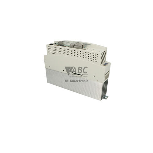
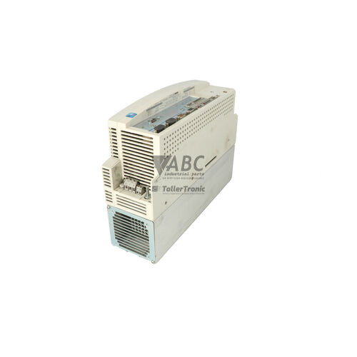
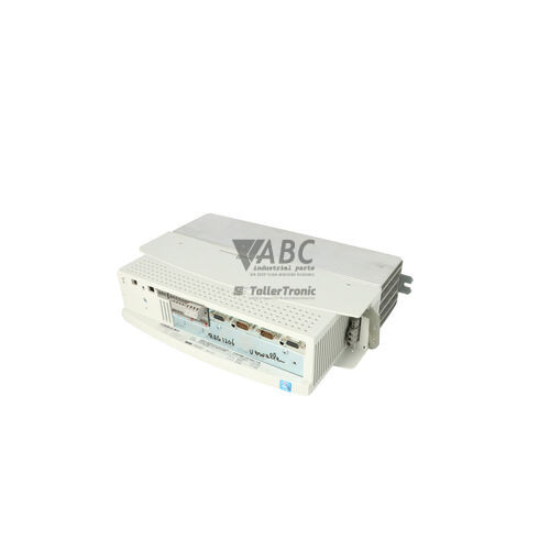
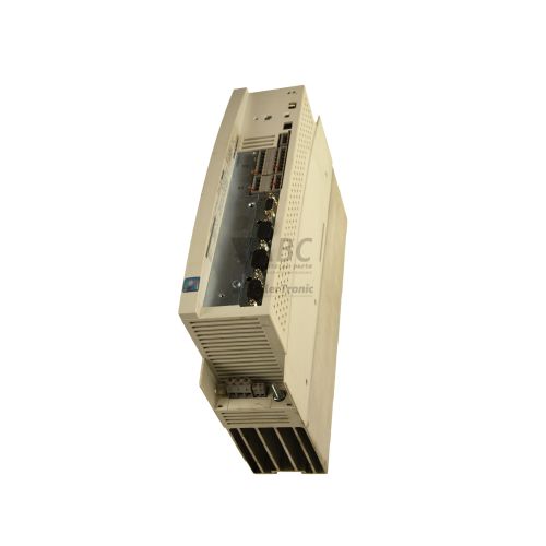
Lenze ESMD112L4TXA 13188428 Frequency Inverter – smD Series 1.1 kW


Het item werd toegevoegd aan uw offerteaanvraag
Product Information
The Lenze ESMD112L4TXA (part number 13188428) is a compact AC frequency inverter from the Lenze smD product family, engineered for variable speed control of 3-phase asynchronous induction motors up to 1.1 kW (1.5 HP). Designed with an IP20 enclosure rating for DIN rail or backplate panel mounting inside control cabinets, this drive operates across a wide 3-phase supply voltage range of 320 V AC to 515 V AC, making it suitable for both 400 V and 480 V industrial power systems. It provides V/f characteristic control with linear or quadratic curves, delivering continuous output currents of 3.0 A at 400 V AC and 2.5 A at 480 V AC over an output frequency range of 0 to 240 Hz at an 8 kHz nominal switching frequency. An integrated Class A EMC line filter minimizes mains frequency interference without requiring external filter hardware.
Control interfacing on the drive includes four programmable digital inputs, one configurable analog input accepting 0–10 V, 0–20 mA, or 4–20 mA signals, and one programmable relay output with a normally open contact rated for 250 V AC at 3 A. Commissioning a replacement unit is streamlined by Lenze's pluggable Electronic Programmable Module (EPM). This EEPROM chip stores all user parameter settings directly on the front panel of the unit. When replacing a drive in production, the original EPM chip can be removed and inserted into the spare ESMD112L4TXA without requiring power, complex cabling, or commissioning software. Parameter sets can also be programmed offline using the EEPM1RA EPM Programmer tool. ABC Industrial Parts can assist maintenance teams with donor units and parameter extraction from donor memory modules when restoring legacy machinery.
Diagnostic feedback and system status are indicated directly through the front-mounted operator panel, which features a 3-digit LED segment display capable of displaying operating values such as current frequency, OFF or STOP status, and numeric trip codes from F1 through F12. Primary field troubleshooting involves checking mains input line voltage across all three phases, verifying motor cable integrity against earth faults or short circuits, inspecting external fault input circuits, and confirming proper EPM module seating. If configuration conflicts occur, restoring parameter defaults via parameter P199 clears memory errors. Severe internal component failures, indicated by fault code F9, are not field-serviceable, making drive replacement or expert repair through ABC Industrial Parts the most efficient path back to operation.
Technical Specifications
| Manufacturer | Lenze |
| Part Number | 13188428 |
| Model / Type | ESMD112L4TXA |
| Product Family | smD |
| Component Type | Frequency Inverter |
| Rated Power (kW) | 1.1 kW |
| Rated Power (HP) | 1.5 hp |
| Supply Voltage Range | 320 - 515 V AC |
| Rated Input Current at 400V | 3.9 A |
| Rated Input Current at 480V | 3.2 A |
| Continuous Output Current at 400V | 3.0 A |
| Continuous Output Current at 480V | 2.5 A |
| Output Frequency Range | 0 - 240 Hz |
| Nominal Switching Frequency | 8 kHz |
| Control Method | V/f characteristic control (linear or quadratic) |
| Digital Inputs | 4 |
| Analog Inputs | 1 (0-10V, 0-20mA, or 4-20mA) |
| Relay Outputs | 1 (NO contact, 250 VAC, 3 A) |
| Integrated EMC Filter | Class A Line Filter |
| Enclosure Protection Rating | IP20 |
| Mounting Type | DIN rail or panel mounting |
Programming and Configuration
Parameter setup on the Lenze ESMD112L4TXA frequency inverter is accomplished using the integrated keypad and 3-digit LED segment display on the front panel. Key operational parameters include acceleration and deceleration time ramps, selection of linear or quadratic V/f characteristic curves, motor parameter definitions, and configuration of digital input functions. In the event of parameter memory corruption or conflicting settings (indicated by fault code F11), the unit can be restored to its original factory defaults by invoking parameter P199.
All configured drive settings are stored in the pluggable Electronic Programmable Module (EPM), a removable memory chip located in the front slot of the drive. The EPM architecture allows parameters to be transferred between units without requiring power to the inverter. Off-line cloning, backup, and batch parameter writing can also be performed using the EEPM1RA EPM Programmer tool, enabling spare drives to be prepared prior to installation.
Communication and System Integration
The ESMD112L4TXA inverter features control terminal block connections for integration into automated machinery. The control interface includes four programmable digital inputs for start/stop control, rotation direction, and external fault trip interlocks, along with one configurable analog input supporting 0–10 V DC, 0–20 mA, or 4–20 mA signals for setpoint frequency speed control.
For status output, the drive provides one programmable relay output with a normally open (NO) contact rated for 250 V AC at 3 A, which changes state upon a fault trip or designated operational condition. When fitted with a serial communications module, the drive supports fieldbus system integration; lost communications across this interface trigger trip condition F10.
Diagnostics and Status Indication
Drive status and fault diagnostics on the ESMD112L4TXA are displayed directly via the front 3-digit LED segment display. Under normal operation, the display indicates states such as OFF, STOP, or real-time output frequency. When an alarm or trip condition occurs, the display shifts to show active fault codes ranging from F1 to F12.
In addition to visual codes on the keypad, the programmable output relay switches state on a fault trip to alert external supervisory equipment. Diagnostic procedures involve referencing the active code to isolate motor overload, mains supply unbalance, overtemperature, or memory connection issues.
Status LED Indicators
| LED | Color/Status | Meaning |
|---|---|---|
| 3-digit LED Display | Red/Green LED segment - Active numeric readout | Displays operational status (e.g. OFF, STOP, output frequency) or active fault code (e.g. F1, F2, F8) |
Replacement and Spare Part Considerations
When replacing a failed Lenze ESMD112L4TXA inverter, the pluggable Electronic Programmable Module (EPM) enables hardware swaps without re-commissioning. Removing the existing EPM memory chip from the old unit and inserting it into the replacement drive transfers all stored parameters instantly without needing software tools or line power.
Verify that the replacement drive matches the exact part number (13188428) and power requirements, specifically the 1.1 kW / 1.5 HP power rating and 320 to 515 V AC 3-phase input voltage range. While the smD series is discontinued, Lenze i510 and i550 cabinet frequency inverters serve as recommended successor series when migrating legacy installations.
Error Codes & Fault Codes
The following error codes may be displayed during operation or diagnostics:
| Code | Name | Description | Possible Cause | Recommended Action |
|---|---|---|---|---|
| F1 | Overcurrent | Inverter output current exceeded peak current limit. | Short circuit or earth fault on motor cable; motor overload; acceleration ramp time too short. | Check motor cable for short circuit or ground fault; check motor sizing; increase acceleration time; check mechanical load for binding. |
| F2 | Overvoltage | DC bus voltage exceeded upper safety threshold. | Regenerative energy from motor during deceleration; deceleration time too short; excessive mains supply voltage. | Extend deceleration time ramp; check supply voltage; install brake module / dynamic braking resistor if required. |
| F3 | Undervoltage | DC bus voltage fell below minimum allowable operating threshold. | Mains supply voltage too low; mains power phase loss or temporary power interruption. | Check mains line voltage; verify input wiring and fuses; check for voltage sags on supply network. |
| F4 | Motor Overload (I²t) | Calculated motor thermal load exceeded limit. | Motor operated at high load and low speed for extended period without auxiliary cooling; incorrect motor data entered. | Allow motor to cool; check motor load and mechanical system; verify motor rating parameters. |
| F5 | Inverter Overload (I²t) | Drive continuous output current threshold exceeded thermal limit. | Inverter undersized for connected load; continuous operating current above drive nominal rating. | Reduce drive load; verify drive sizing relative to motor current requirements. |
| F6 | Overtemperature | Inverter heatsink temperature exceeded maximum threshold. | Inadequate cabinet ventilation; ambient temperature too high; cooling fan blocked or failed; heatsink dirty. | Clean heatsink cooling fins; improve panel airflow; check ambient temperature; ensure required mounting clearances. |
| F7 | External Fault | Digital input configured for external fault function was opened. | External trip signal activated (e.g. motor thermistor relay or safety interlock opened). | Check external devices wired to the programmed digital input; reset external fault condition. |
| F8 | EPM Error | Electronic Programmable Module memory missing, unreadable, or corrupted. | EPM chip not inserted correctly; incompatible EPM version; corrupted parameter memory on EPM chip. | Verify EPM module is firmly seated in front slot; replace EPM chip with valid programmed module; perform factory reset/reload. |
| F9 | Internal Fault | Internal hardware or CPU self-test failure detected. | Internal hardware failure or memory corruption. Board-level component damage. | Cycle power to drive. If error persists, internal hardware fault is confirmed — return unit for repair or replace the drive. |
| F10 | Communication Fault | Time-out or loss of communication via serial interface option. | Interrupted fieldbus network connection; incorrect baud rate or station address; cabling fault. | Check communication cable wiring and shield connection; verify master controller operation and timeout settings. |
| F11 | Parameter Fault | Inconsistent or illegal parameter configuration in drive memory. | Conflicting parameter values loaded into memory; invalid EPM format. | Restore factory default parameters (P199) and re-commission drive parameters. |
| F12 | Mains Phase Failure | Phase unbalance or phase loss detected on incoming 3-phase supply. | Blown mains fuse on one input phase; loose supply connection. | Check input supply voltage on all 3 phases; inspect line fuses and wiring terminals. |
Frequently Asked Questions
How do I transfer parameters to a replacement Lenze ESMD112L4TXA drive?
Remove the pluggable blue EPM memory chip from the front panel of the existing drive and insert it into the EPM slot of the replacement ESMD112L4TXA unit. All parameters are transferred immediately without applying power or connecting programming software.
What tools are available for programming EPM memory chips offline?
The EEPM1RA EPM Programmer tool can be used to duplicate, backup, or write parameter files directly to EPM modules offline.
What does fault code F8 mean on the drive display?
Fault code F8 indicates an EPM error. This occurs if the EPM module is missing, inserted incorrectly, unreadable, or corrupted. Ensure the module is firmly seated or replace it with a properly programmed EPM chip.
How can I reset the ESMD112L4TXA drive to factory default settings?
You can restore factory default parameters by setting parameter P199 via the integrated front keypad, clearing invalid or conflicting parameter configurations.
What modern inverter series replaces the discontinued Lenze smD series?
The Lenze i510 and i550 cabinet frequency inverters are the recommended successor series for migrating legacy smD drive installations.
Take advantage of our exchange formula
A defective product does not have to be worthless. At ABC Industrial Parts, you can hand in defective products and immediately benefit from a discount on your new purchase. This is a smart way to save money while contributing to a circular economy.
Play it safe with our warranty conditions
Industrial plants prefer to keep running invariably, no matter what. Therefore, it is essential that you can rely on high-quality products and/or sustainable repairs. With our warranty conditions, you can count on certainty, whether you choose new, used or repaired products.
Data backup and recovery
Have you lost valuable parameters or data due to a malfunction while the manufacturer no longer provides support? At ABC Industrial Parts, we help you secure this data, both for common and specific products.
Specific firmware and hardware versions
If you are working with specific hardware or firmware versions that are no longer available from the manufacturer, ABC Industrial Parts is your partner. When making your enquiry, clearly state which versions you need, we will then look at the possibilities of supplying those versions, so that your installations continue to function optimally.
Disclaimer:
We are not an authorised distributor of Lenze.
Product photos are for illustration purposes only and may differ from the actual product delivered.
Some of the content on this page was created with the help of AI. While we strive to provide accurate and up-to-date information, errors may occur.