Lenze 13190126 E82ZAFVC010 – System Bus (CAN) Function Module


Het item werd toegevoegd aan uw offerteaanvraag
Product Information
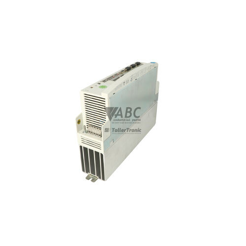
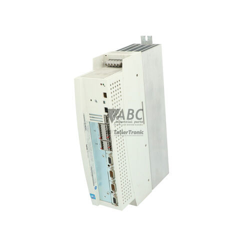
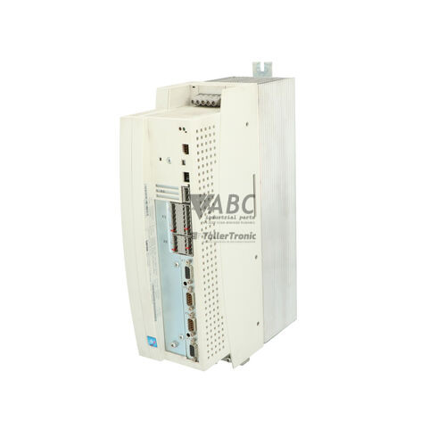
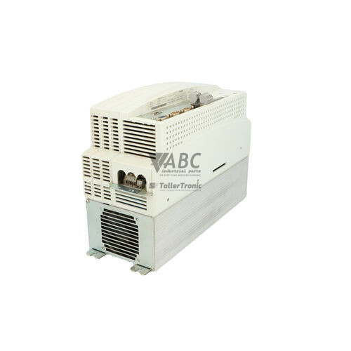
The Lenze 13190126 E82ZAFVC010 is a CAN System Bus function module engineered for Lenze 8200 vector frequency inverters spanning power ranges from 0.25 kW to 90 kW. Operating as a plug-in communication interface, the module mounts directly into the host drive's standardized Function Module Slot (FIF) and receives internal logic power directly from the inverter host slot. Designed to facilitate inter-drive networking, real-time motion synchronization, and distributed control across automated machinery, this component eliminates the need for external power supplies while minimizing cabinet wiring complexity.
For system integration, the module features a 5-pole pluggable screw terminal block supporting CAN-H, CAN-L, GND, and shield connections. Built on the ISO 11898 physical layer, it supports both the Lenze System Bus protocol and standard CANopen DS301 profile communication across a linear bus topology with up to 63 addressing nodes and configurable transmission speeds up to 500 kbit/s. Commissioning a replacement unit involves setting the network node ID and baud rate via Lenze Global Drive Control (GDC) software or the local Keypad XT (E82ZBC). Because operating configurations reside in the host drive's non-volatile EEPROM, hardware replacement is straightforward, and ABC Industrial Parts can assist in sourcing tested replacement modules to restore machine operation quickly.
Real-time status monitoring is provided by front-panel LED indicators and drive diagnostic parameters. A green CAN RUN LED signals pre-operational or operational network states, while a red CAN ERR LED alerts maintenance personnel to bus-off conditions, warning thresholds, or guard timeouts. First-line troubleshooting includes verifying fieldbus cable routing away from power wiring, inspecting 120 Ohm termination resistors on both physical bus ends, and reviewing drive diagnostic parameters C0359 and C0361. When persistent communication errors indicate an internal module failure, procuring a tested replacement from ABC Industrial Parts provides a direct route back to full production.
Technical Specifications
| Manufacturer | Lenze |
| Part Number | 13190126 |
| Model/Type | E82ZAFVC010 |
| Component Type | Communication Module |
| Product Family | 8200 vector |
| Bus System | Lenze System Bus (CAN / ISO 11898) |
| Maximum Baud Rate | 500 kbit/s |
| Maximum Node Address | 63 |
| Bus Topology | Line structure with 120 Ohm termination at both ends |
| Interface Connector | 5-pole Pluggable Screw Terminal |
| Internal Power Supply | Powered via host drive FIF slot |
| Lifecycle Status | Discontinued |
Programming and Configuration
Configuration of the Lenze 13190126 E82ZAFVC010 module is managed through Lenze Global Drive Control (GDC) commissioning software or locally via the Keypad XT (E82ZBC) operating unit. Network settings, such as assigning a unique node ID up to address 63 and setting transmission speeds across 20, 50, 125, 250, or 500 kbit/s, are configured using drive parameters such as C0351.
Because network configurations are stored within the non-volatile EEPROM memory of the host 8200 vector frequency inverter, replacing a damaged module does not require loading firmware or downloading project files directly into the module. Once a replacement E82ZAFVC010 is seated into the Function Module Slot (FIF), it utilizes the parameters stored in the drive.
Communication and System Integration
Operating on the CAN 2.0B physical layer conforming to ISO 11898 standards, the E82ZAFVC010 supports both Lenze System Bus protocol and standard CANopen DS301 profiles. It provides motion synchronization, remote parameterization, and distributed control across multi-drive assemblies in material handling, packaging, textile processing, and automotive applications.
Fieldbus wiring connects via a 5-pole pluggable screw terminal block containing terminals for CAN-H, CAN-L, ground, and cable shielding. Network layout follows a linear bus topology, requiring standard 120 Ohm termination resistors placed across the signal lines at both physical end nodes to prevent transmission reflections.
Diagnostics and Status Indication
The E82ZAFVC010 features front-panel LEDs for real-time status monitoring. Internal diagnostic monitoring can also be accessed via Global Drive Control (GDC) or Keypad XT (E82ZBC) by referencing drive diagnostic parameter C0359 for CAN status and parameter C0361 for the CAN error counter.
Status LED Indicators
| LED | Color/Status | Meaning |
|---|---|---|
| CAN RUN | Green - Blinking / Solid ON | Blinking indicates Pre-Operational state; Solid ON indicates Operational state (active CAN communication) |
| CAN ERR | Red - ON / Flashing | Communication error on CAN bus (Bus-Off, Warning limit reached, or guard timeout) |
Replacement and Spare Part Considerations
When replacing an E82ZAFVC010 system bus module, installation is simplified by the pluggable screw terminal block. Technicians can remove the wiring connector without disconnecting individual conductors, avoiding potential rewiring mistakes.
Because operating configurations reside in the host Lenze 8200 vector inverter's EEPROM, replacing the hardware unit requires no separate parameter download. After inserting the replacement module into the drive's FIF slot, verify physical connections, termination resistor presence on network ends, and check that status LEDs indicate active bus communication upon power-up.
Error Codes & Fault Codes
The following error codes may be displayed during operation or diagnostics:
| Code | Name | Description | Possible Cause | Recommended Action |
|---|---|---|---|---|
| CE0 | CAN Communication Error / Bus Off | System bus (CAN) communication interrupted or drive entered Bus-Off state due to excessive transmit/receive errors | Incorrect baud rate, defective cable, missing 120 Ohm termination resistors, excessive electromagnetic noise | Check wiring, check shield connection, verify 120 Ohm termination resistors on end nodes, verify set baud rate in C0351. |
| CE1 | CAN Time-Out (CAN Object 1) | Process data object 1 (CAN-IN1) did not arrive within configured monitoring time | Master / sender stopped transmitting, bus overload, cable disconnection | Check master device state, inspect cabling, check monitoring time settings in drive parameters. |
| CE2 | CAN Time-Out (CAN Object 2) | Process data object 2 (CAN-IN2) did not arrive within configured monitoring time | Transmitter stopped sending, network interruption | Check transmitting node and network wiring. |
| CE3 | CAN Time-Out (CAN Object 3) | Process data object 3 (CAN-IN3) did not arrive within configured monitoring time | Transmitter failure or network segment fault | Check transmitting node status and fieldbus connections. |
| CE4 | CAN Bus Warning Limit Reached | CAN controller error counter exceeded internal warning threshold | Sporadic transmission errors, noisy environment, incorrect cable impedance | Check fieldbus cable routing away from power cables, ensure proper grounding and termination. |
Frequently Asked Questions
Which drive series supports the Lenze 13190126 E82ZAFVC010 module?
The E82ZAFVC010 is designed specifically for Lenze 8200 vector frequency inverters across power ranges from 0.25 kW to 90 kW, connecting directly via the drive's Function Module Slot (FIF).
Does the E82ZAFVC010 require an external supply voltage?
No, the module receives logic power directly from the host 8200 vector inverter through its internal FIF slot connection.
How are parameter settings transferred when installing a replacement module?
All communication parameters, including node address and baud rate settings, are stored in the host inverter's non-volatile EEPROM. Replacing the module requires no individual parameter downloads.
What cable termination is required for the CAN system bus?
The linear bus topology requires 120 Ohm termination resistors installed across CAN-H and CAN-L at both physical end nodes of the network.
What do the CAN RUN and CAN ERR LEDs indicate?
The green CAN RUN LED indicates Pre-Operational (blinking) or Operational (solid ON) status. The red CAN ERR LED indicates bus communication errors such as bus-off, warning limits, or guard timeouts.
Take advantage of our exchange formula
A defective product does not have to be worthless. At ABC Industrial Parts, you can hand in defective products and immediately benefit from a discount on your new purchase. This is a smart way to save money while contributing to a circular economy.
Play it safe with our warranty conditions
Industrial plants prefer to keep running invariably, no matter what. Therefore, it is essential that you can rely on high-quality products and/or sustainable repairs. With our warranty conditions, you can count on certainty, whether you choose new, used or repaired products.
Data backup and recovery
Have you lost valuable parameters or data due to a malfunction while the manufacturer no longer provides support? At ABC Industrial Parts, we help you secure this data, both for common and specific products.
Specific firmware and hardware versions
If you are working with specific hardware or firmware versions that are no longer available from the manufacturer, ABC Industrial Parts is your partner. When making your enquiry, clearly state which versions you need, we will then look at the possibilities of supplying those versions, so that your installations continue to function optimally.
Disclaimer:
We are not an authorised distributor of Lenze.
Product photos are for illustration purposes only and may differ from the actual product delivered.
Some of the content on this page was created with the help of AI. While we strive to provide accurate and up-to-date information, errors may occur.