Lenze 13462362 9324MP.2G.91 9300 Servo Drive Board


Het item werd toegevoegd aan uw offerteaanvraag
Product Information
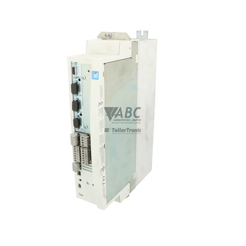
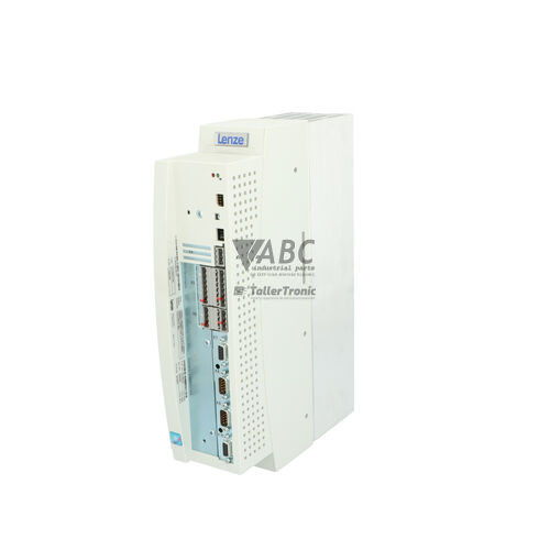
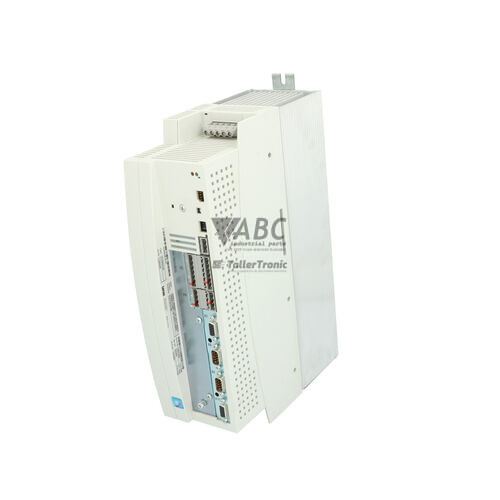
The Lenze 13462362 (Model 9324MP.2G.91) is an internal drive board engineered specifically for installation within Lenze 9300 Servo series controllers, designed for frame size 9324 assemblies such as the EVF9324 and EVS9324 inverters. Built to manage 5.5 kW motion control operations, this internal power and signal processing module controls power stage driving, regulation circuits, and system bus interfaces across an AC supply voltage range of 320 to 528 V AC (nominal 3x 400/480 V AC). Operating with a rated input current of 13 A and delivering a continuous output current of 11 A at an 8 kHz switching frequency, this board serves as a core replacement component for machinery in packaging, textile, material handling, and automotive manufacturing lines.
Interfacing within the inverter frame through a multi-pin PCB header and card edge layout, the module features an integrated CAN system bus connection for rapid internal inter-board communication. Putting a replacement 9324MP.2G.91 board into service requires restoring application parameters into its four non-volatile EEPROM memory profiles. Parameter backups can be extracted and restored using the Keypad XT (EMF2102IB) or Lenze Global Drive Control (GDC) software via a system bus adapter interface. When mounting the module to the internal heatsink, proper installation requires removing old compound and applying a fresh, uniform layer of thermal grease across the contact surface. ABC Industrial Parts provides technical support for preparing replacement boards and carrying out parameter transfers.
Drive operational status is displayed on the unit's front face through status LEDs including DRIVE READY, DRIVE ERROR, and CAN BUS STATUS, which indicate system power readiness, active trip conditions, and fieldbus communication state. Technicians can review active trip registers and history buffers using the Keypad XT module or GDC software. Common protective trips such as OC1 (short circuit), OU (DC bus overvoltage), OH (heatsink overtemperature), or CE0 (CAN communication error) assist in identifying external wiring, motor insulation, or cooling issues. If faults like OC1 persist with the motor disconnected or if internal system codes such as EER or H05 occur, hardware-level board damage is present, making a complete board replacement or tested exchange unit from ABC Industrial Parts the most efficient path back to production.
Technical Specifications
| Manufacturer | Lenze |
| Part Number | 13462362 |
| Model / Type | 9324MP.2G.91 |
| Component Type | Drive Board |
| Product Family | 9300 Servo |
| Rated Power | 5.5 kW |
| Supply Voltage Range | 320 - 528 V AC (3x 400/480 V AC nominal) |
| Rated Input Current | 13 A |
| Continuous Output Current | 11 A |
| Switching Frequency | 8 kHz (Selectable 4 kHz, 8 kHz, 16 kHz) |
| Interface Connector Type | Multi-pin PCB Header / Card Edge |
| Communication Bus | Integrated CAN System Bus |
| Memory | 4 Internal Non-Volatile EEPROM Parameter Sets |
Programming and Configuration
Configuration management for the Lenze 13462362 drive board relies on four internal non-volatile EEPROM parameter sets stored within the drive architecture. When installing a replacement card inside an EVF9324 or EVS9324 inverter assembly, matching the drive's parameter set to the original machine profile is necessary to restore correct motor limits, control loop gains, and switching parameters.
Parameter transfer and backup procedures are performed using either the portable EMF2102IB Keypad XT module or a PC operating Lenze Global Drive Control (GDC) software connected via a system bus adapter. In cases where the original hardware has failed completely and parameters cannot be extracted, factory default parameters can be reloaded to the non-volatile memory before inputting machine-specific operational parameters.
Communication and System Integration
The 9324MP.2G.91 board connects to the main control card and internal inverter components using a multi-pin PCB header and card edge connector layout. This physical interface carries gating signals, voltage feedback, thermal sensor signals, and control bus communications directly through internal PCB traces.
For network and inter-module coordination, the board includes integrated CAN system bus connectivity. It supports selectable PWM switching frequencies of 4 kHz, 8 kHz, and 16 kHz, allowing engineers to balance thermal dissipation inside the drive cabinet against high-frequency motor acoustic noise requirements.
Diagnostics and Status Indication
System state monitoring on the 13462362 board is provided by onboard diagnostic LEDs alongside register-based fault logging. Front-panel status indicators provide immediate visual status for power stage readiness, drive trip state, and internal or external CAN system bus activity.
In-depth troubleshooting can be conducted using the Keypad XT module or Lenze Global Drive Control (GDC) software. Reading the active fault code register or analyzing the historical fault log stored in memory allows technicians to isolate external line faults, output short circuits, and internal hardware conditions.
Status LED Indicators
| LED | Color/Status | Meaning |
|---|---|---|
| DRIVE READY | Indicates power stage and controller operational readiness | |
| DRIVE ERROR | Indicates drive trip or active fault condition | |
| CAN BUS STATUS | Indicates internal/external CAN system bus communication state |
Replacement and Spare Part Considerations
Installing the 13462362 internal drive board enables component-level refurbishment of 5.5 kW Lenze 9300 Servo inverters (size 9324) without requiring replacement of the entire chassis assembly. Technicians must verify that the replacement PCB carries the matching 9324MP.2G.91 model designation to confirm exact power stage and internal connector alignment.
Thermal surface preparation is a critical step in the physical replacement process. Old thermal compound must be completely removed from the inverter heatsink surface, and a thin, uniform coating of fresh thermal grease must be applied across the board thermal interface prior to mechanical mounting. Once physically installed, parameter backup files must be loaded into the non-volatile memory using the EMF2102IB Keypad XT or GDC software before restoring system power.
Error Codes & Fault Codes
The following error codes may be displayed during operation or diagnostics:
| Code | Name | Description | Possible Cause | Recommended Action |
|---|---|---|---|---|
| OC1 | Short Circuit | Short circuit at motor output terminals or ground fault. | Motor cable short circuit, motor winding fault, or internal inverter power stage failure. | Check motor power wiring and insulation. Disconnect motor and re-test drive. If OC1 persists with motor disconnected, internal hardware fault requires board or unit repair. |
| OC2 | Earth Fault | Earth fault / ground fault detected on output phase. | Insulation breakdown in motor winding, motor cable damage, or high capacitive leakage current. | Check cable and motor insulation resistance with megohmmeter. |
| OU | Overvoltage DC Bus | DC bus voltage exceeds upper threshold limit. | Regenerative energy from decelerating motor exceeds braking module capacity or brake resistor circuit open. | Check deceleration ramps, braking transistor operation, and external brake resistor connection. |
| LU | Undervoltage DC Bus | DC bus voltage falls below lower threshold limit. | Mains supply voltage drop, phase loss, or main contactor open. | Verify incoming AC line supply line-to-line voltage and fuses. |
| OH | Heatsink Overtemperature | Drive heatsink temperature has exceeded maximum safe operating threshold. | Insufficient cooling airflow, dirty heatsink fins, failed cooling fan, or high ambient temperature. | Clean heatsink, inspect enclosure cooling fans, ensure proper clearance around drive enclosure. |
| OH4 | Drive Thermal Overload (I x t) | Calculated drive thermal load limit reached. | Continuous operation above rated current capacity. | Check mechanical load for jam/binding; verify motor sizing and acceleration parameters. |
| CE0 | CAN Bus Communication Error | Communication interruption or bus-off condition on CAN system bus. | Damaged CAN cable, incorrect bus termination resistors, high electrical noise, or node address mismatch. | Check CAN bus wiring, 120 ohm termination resistors at bus ends, and baud rate settings. |
| EER | EEPROM Memory Error | Internal EEPROM checksum error or parameter read/write failure. | Internal non-volatile memory corruption or hardware component failure. | Reload factory default parameters and reconfigure. If fault persists, internal control/drive board hardware fault exists requiring service or replacement. |
| H05 | Internal Hardware Error | Hardware fault detected on drive power board or control card interface. | Internal component failure, corrupted board identification hardware, or board mismatch. | Internal hardware fault — repair or replacement of drive board / controller required. |
Frequently Asked Questions
Which Lenze drive units use the 13462362 drive board?
The 13462362 (Model 9324MP.2G.91) is designed as an internal power and control board for 5.5 kW Lenze 9300 Servo series controllers in frame size 9324, specifically EVF9324 and EVS9324 inverters.
How are parameters backed up and transferred when replacing this board?
Parameters stored in the non-volatile EEPROM memory can be saved and restored using the Lenze Keypad XT (EMF2102IB) or Lenze Global Drive Control (GDC) software via a PC and system bus adapter.
What thermal preparation is required during installation?
When mounting the replacement board to the heatsink, existing thermal paste must be cleaned off entirely and a fresh, even coat of thermal grease applied across the interface to prevent thermal tripping.
What does fault code OC1 indicate on this drive module?
OC1 indicates an overcurrent or output short circuit. If OC1 remains present after disconnecting the motor leads, an internal power stage failure on the board requires board repair or replacement.
What PWM switching frequencies does the 9324MP.2G.91 board support?
The board operates at a default switching frequency of 8 kHz and supports selectable frequencies of 4 kHz, 8 kHz, and 16 kHz.
Take advantage of our exchange formula
A defective product does not have to be worthless. At ABC Industrial Parts, you can hand in defective products and immediately benefit from a discount on your new purchase. This is a smart way to save money while contributing to a circular economy.
Play it safe with our warranty conditions
Industrial plants prefer to keep running invariably, no matter what. Therefore, it is essential that you can rely on high-quality products and/or sustainable repairs. With our warranty conditions, you can count on certainty, whether you choose new, used or repaired products.
Data backup and recovery
Have you lost valuable parameters or data due to a malfunction while the manufacturer no longer provides support? At ABC Industrial Parts, we help you secure this data, both for common and specific products.
Specific firmware and hardware versions
If you are working with specific hardware or firmware versions that are no longer available from the manufacturer, ABC Industrial Parts is your partner. When making your enquiry, clearly state which versions you need, we will then look at the possibilities of supplying those versions, so that your installations continue to function optimally.
Disclaimer:
We are not an authorised distributor of Lenze.
Product photos are for illustration purposes only and may differ from the actual product delivered.
Some of the content on this page was created with the help of AI. While we strive to provide accurate and up-to-date information, errors may occur.