Siemens LFL1.635 Burner Control Unit


Het item werd toegevoegd aan uw offerteaanvraag
Product Information
The Siemens LFL1.635 is a motor-driven burner control unit engineered for forced draft gas, oil, or dual-fuel burner sequencing in medium- to high-capacity thermal applications. Operating within an AC voltage range of 187 to 264 V AC (220–240 V AC nominal) at 50 to 60 Hz with a power consumption of 3.5 VA, this controller governs sequence execution, air damper positioning, ignition, and fuel valve controls. Designed with an IP40 protection rating when installed on its base, the module provides reliable control across commercial HVAC, district heating systems, industrial steam boilers, and thermal process plants.
Installing or replacing an LFL1.635 relies on a standard plug-in base design compatible with the Siemens AGK11 baseplate. Sequence timing is managed mechanically using an integrated motor-driven sequence switch, eliminating the need for software programming, parameter downloading, or firmware configuration during field installation. The control unit accommodates multiple flame sensing technologies, including ionization probes, Siemens QRA2, QRA10, QRA53, and QRA55 UV sensors, and RAR7 or RAR8 selenium photocell detectors. Swapping a damaged controller is accomplished by unplugging the legacy unit from the AGK11 base and securing the spare without altering existing field wiring. Expert assistance from ABC Industrial Parts can assist facilities in sourcing ready-to-install replacement units.
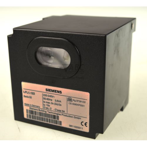
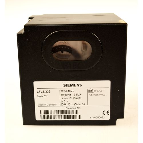
Field diagnostics are provided by a mechanical sequence indicator disk visible through a front housing viewing window. The sequence disk turns as the unit progresses through operational stages—including positions a, b, c, d, and P—and stops at explicit symbol markers if a safety shutdown occurs. Safety lockouts are simultaneously indicated by a solid red light built directly into the front reset button. When recurring lockouts stem from internal amplifier faults or mechanical drive wear, internal repairs are not field-serviceable, making unit replacement or exchange through ABC Industrial Parts the recommended solution to restore operation.
Technical Specifications
| Manufacturer | Siemens |
| Part number | LFL1.635 |
| Model / Type | Burner Control |
| Product family | LFL |
| Supply voltage range | 187 – 264 V AC (220 – 240 V AC nominal) |
| Supply frequency | 50 – 60 Hz |
| Power consumption | 3.5 VA |
| Pre-purge time (t1) | 66 s |
| Safety time (t2) | 2.5 s |
| Pre-ignition time (t3) | 2.5 s |
| Post-ignition time (t3n) | 2.5 s |
| Interval t4 | 12.5 s |
| Interval t5 | 12.5 s |
| Post-purge time (t6) | 15 s |
| Start command delay (t7) | 2.5 s |
| Air pressure verification time (t10) | 10 s |
| Permissible post-combustion time (t13) | 15 s |
| Ingress protection rating | IP40 |
| Compatible plug-in base | Siemens AGK11 |
Diagnostics and Status Indication
The Siemens LFL1.635 features visual diagnostic monitoring through a front-facing viewing window on the housing. An internal mechanical sequence disk rotates behind the window during operation, clearly displaying operational phases designated as a, b, c, d, and P. When a safety shutdown takes place, the sequence disk stops at a specific symbol marker corresponding to the exact sequence step where the fault was detected, allowing technicians to determine the fault cause without additional diagnostic tools.
In addition to mechanical disk position tracking, the unit includes an integrated lockout indicator lamp built into the illuminated red reset button located on the front panel. Upon experiencing an operational lockout, the reset button lights up solid red. Pressing this button resets the mechanical sequence mechanism after the underlying fault condition has been addressed.
Status LED Indicators
| LED | Color/Status | Meaning |
|---|---|---|
| LOCKOUT / RESET | Red - Solid | Fault lockout indicator lamp integrated into internal reset button |
Replacement and Spare Part Considerations
When selecting a replacement burner control unit, matching the exact part number LFL1.635 is necessary to maintain precise system safety and timing parameters. Variations across burner control series feature different fixed pre-purge times, safety intervals, or terminal assignments. The LFL1.635 provides a 66-second pre-purge period (t1) and a 2.5-second safety time (t2); substituting a controller with different fixed sequence timing will alter purge and ignition behavior.
Replacing an installed unit is straightforward due to the plug-in architecture using the Siemens AGK11 baseplate. The control unit can be unclipped and removed from the base without rewiring field connections. Prior to commissioning the spare, technicians should inspect the AGK11 base terminals for heat damage or corrosion, verify that the flame sensor (ionization, UV probe QRA series, or selenium photocell RAR series) is clean, and confirm that the air pressure switch functions properly.
Error Codes & Fault Codes
The following error codes may be displayed during operation or diagnostics:
| Code | Name | Description | Possible Cause | Recommended Action |
|---|---|---|---|---|
| ▲ at start / standby / position a | Extraneous Light / Premature Flame Signal | Lockout during pre-purge or standby before burner startup sequence is completed. | Flame sensor detects extraneous light or premature flame signal, faulty flame detector, defective internal flame signal amplifier. | Check for extraneous light sources, clean or inspect flame detector, replace flame sensor. If error persists with no light present, replace burner control unit. |
| ▲ at position P | Air Pressure Failure | Lockout caused by missing air pressure switch signal. | Air pressure switch contact failed to close within interval t10, or opened during pre-purge or operation. | Check air pressure switch setting and contacts, check fan operation and air ducts, verify wiring to air pressure switch. |
| ▲ at position c | Ignition Failure / No Flame Signal | Lockout at the end of safety time t2. | No flame established during safety time t2, fuel valve failure, ignition transformer or electrode defect, faulty flame sensor. | Check fuel supply and fuel solenoid valves, inspect ignition spark and ignition electrodes, check flame sensor alignment and clean sensor. |
| ▲ at position d | Flame Failure During Operation | Lockout during normal operating phase. | Loss of flame during burner operation, fuel interruption, faulty flame detector or amplifier. | Check fuel supply pressure, check burner stability and air-fuel ratio, check flame detector cleanliness and wiring. |
| ▲ at position post-purge / t6 / t13 | After-Burning / Post-Combustion Flame Signal | Lockout during post-purge phase t6. | Fuel valve leaking or failing to close completely, persistent post-combustion flame signal detected after shutdown. | Inspect fuel shutoff valves for tightness/leakage, repair or replace leaking fuel valves. |
Frequently Asked Questions
How do you identify the cause of a lockout on the Siemens LFL1.635?
Lockout causes are determined by inspecting the mechanical sequence indicator disk through the front viewing window on the housing. The disk stops at specific phase position markers (such as a, P, c, d, or post-purge phase symbols) corresponding to where the fault occurred, while the illuminated red reset button confirms a lockout state.
Does replacing a Siemens LFL1.635 require software or firmware configuration?
No software or firmware setup is required. The LFL1.635 uses an internal motor-driven cam switch to govern sequence timing mechanically. A replacement device is installed by plugging it directly onto the existing AGK11 baseplate.
Which flame sensors are compatible with the LFL1.635 control unit?
The LFL1.635 supports ionization probes, Siemens QRA2, QRA10, QRA53, and QRA55 UV flame detectors, as well as Siemens RAR7 and RAR8 selenium photocell detectors.
What are the primary sequence timing specifications for the LFL1.635?
Fixed sequence timing specs include a 66-second pre-purge time (t1), a 2.5-second safety time (t2), a 2.5-second pre-ignition time (t3), a 15-second post-purge time (t6), and a 10-second air pressure verification time (t10).
What action should be taken if the sequence disk indicates a lockout at position P?
A lockout at position P indicates an air pressure failure. Inspect the air pressure switch settings and contacts, check burner fan operation and air duct paths, and verify wiring connections between the pressure switch and the control baseplate.
Take advantage of our exchange formula
A defective product does not have to be worthless. At ABC Industrial Parts, you can hand in defective products and immediately benefit from a discount on your new purchase. This is a smart way to save money while contributing to a circular economy.
Play it safe with our warranty conditions
Industrial plants prefer to keep running invariably, no matter what. Therefore, it is essential that you can rely on high-quality products and/or sustainable repairs. With our warranty conditions, you can count on certainty, whether you choose new, used or repaired products.
Data backup and recovery
Have you lost valuable parameters or data due to a malfunction while the manufacturer no longer provides support? At ABC Industrial Parts, we help you secure this data, both for common and specific products.
Specific firmware and hardware versions
If you are working with specific hardware or firmware versions that are no longer available from the manufacturer, ABC Industrial Parts is your partner. When making your enquiry, clearly state which versions you need, we will then look at the possibilities of supplying those versions, so that your installations continue to function optimally.
Disclaimer:
We are not an authorised distributor of Siemens.
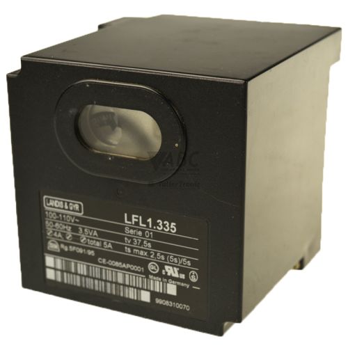
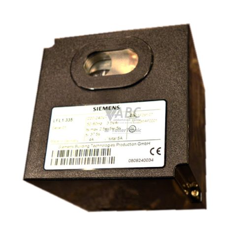
Product photos are for illustration purposes only and may differ from the actual product delivered.
Some of the content on this page was created with the help of AI. While we strive to provide accurate and up-to-date information, errors may occur.