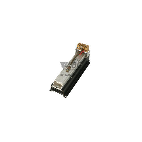
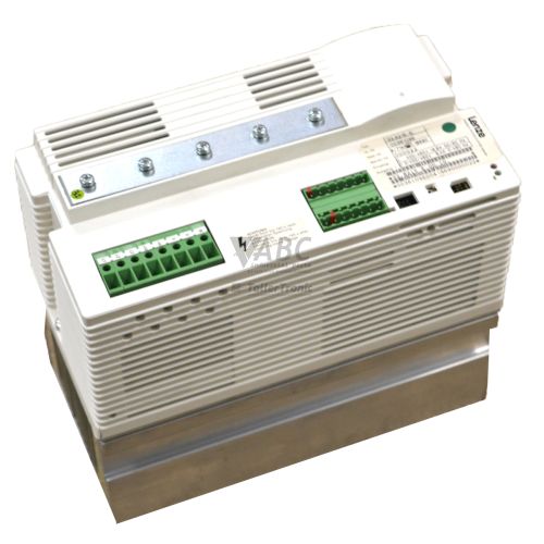
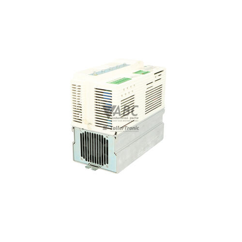
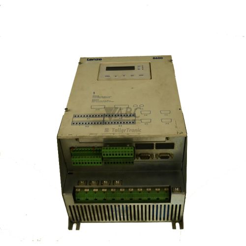
Lenze 00361657 33.8602_E Regenerative Power Supply Unit


Het item werd toegevoegd aan uw offerteaanvraag
Product Information
The Lenze 00361657 (Model 33.8602_E) is a line-synchronized power supply and regenerative feedback unit designed for shared DC bus drive systems within the Lenze 8600 series. Rated for 10 kW continuous power and 18 A nominal current, this unit supplies power to connected frequency inverters while feeding surplus dynamic braking energy directly back into the three-phase AC power grid. Built in an IP20 cabinet enclosure, it operates across a nominal input supply range of 400 V AC to 480 V AC (with operational tolerances from 320 V AC to 528 V AC) and delivers a DC link voltage between 530 V DC and 750 V DC. By replacing traditional braking resistors with regenerative energy recovery, the unit eliminates excessive thermal accumulation inside control cabinets and lowers overall operating energy costs.
Integrating the module into a multi-inverter configuration requires robust connections across both AC mains and the common DC bus. AC line power and DC bus links (+UG, -UG) are attached via screw terminal connections, with external Lenze mains commutation chokes placed in line to ensure smooth grid interaction. The unit communicates its operational readiness and trip status to an upper-level PLC through potential-free relay contact outputs. Replacing a failed unit involves mechanical mounting, securing terminal blocks, and confirming compatible line voltage and choke configurations. Facility technicians can source tested replacement hardware or arrange professional repair through ABC Industrial Parts to restore drive system operation without extended line stoppage.
Visual operational feedback is provided via three front-panel status LEDs indicating system readiness, active regeneration, and error conditions. Diagnostic outputs signal internal parameters, while local fault monitoring detects overvoltage (Umax), mains undervoltage or phase failure (Umin), heatsink overtemperature (OH), and overcurrent or power stage faults (Imax / Short Circuit). Basic troubleshooting involves checking input line voltage, line fuses, contactor circuits, cabinet airflow, and DC link wiring. When an overcurrent or internal power stage fault persists following external checks, internal hardware damage is present and field servicing is not possible, making unit exchange or expert repair via ABC Industrial Parts the effective route back to production.
Technical Specifications
| Manufacturer | Lenze |
| Part Number | 00361657 |
| Model/Type | 33.8602_E |
| Component Type | Regenerative Power Supply Unit |
| Product Family | Lenze 8600 |
| Nominal Supply Voltage Range | 400 - 480 V AC (3-phase) |
| Operating Voltage Range | 320 - 528 V AC |
| DC Link Output Voltage | 530 - 750 V DC |
| Rated Power Output | 10 kW |
| Peak Power Output | 15 kW (up to 60 s) |
| Rated Current | 18 A |
| Protection Rating | IP20 |
Communication and System Integration
The Lenze 00361657 (33.8602_E) connects into multi-axis drive architectures via standard screw terminal connections for three-phase AC input and DC bus links labeled +UG and -UG. Designed for operation alongside Lenze 8600 series frequency inverters, the module acts as a central DC bus power supply while enabling continuous grid-synchronized power recovery during motor deceleration phases.
System monitoring and higher-level integration rely on integrated potential-free relay contact outputs. These contacts provide clear status signals (Ready/OK and Fault) directly to a programmable logic controller (PLC) or main system supervisor. External Lenze mains commutation chokes are utilized on the AC side to ensure line synchronization and limit harmonic interactions with the electrical grid.
Diagnostics and Status Indication
Front-panel status LEDs provide immediate diagnostic feedback for operators and maintenance personnel. A green Betrieb/Ready LED signals active mains supply and operational readiness, while a yellow Rückspeisung/Regen LED indicates active power feedback into the utility grid. A solid red Störung/Fault LED alerts to fault conditions such as voltage limits, thermal overload, or power stage trips.
In addition to visual indicators, internal diagnostic logic drives potential-free relay outputs for remote system monitoring. If the red fault LED remains lit continuously and external electrical checks reveal no installation faults, an internal power semiconductor or control board failure is present.
Status LED Indicators
| LED | Color/Status | Meaning |
|---|---|---|
| Betrieb / Ready | Green - Solid | Mains power supply present and unit ready for operation. |
| Rückspeisung / Regen | Yellow - Solid / Flashing | Regenerative feedback actively operating (power being returned to mains). |
| Störung / Fault | Red - Solid | Active error state such as overvoltage, undervoltage, thermal overload, or internal hardware error. If lit continuously without external fault cause, indicates non-serviceable internal board failure requiring unit repair/replacement. |
Replacement and Spare Part Considerations
When replacing a Lenze 00361657 (33.8602_E) unit, confirm that the replacement module matches the exact part number and power rating. The replacement unit must handle a continuous 10 kW regenerative load (18 A nominal) and support peak braking demands up to 15 kW for up to 60 seconds. Verify that mains supply lines match the 400 V AC to 480 V AC nominal specification.
Ensure screw terminal block wiring for the DC bus (+UG, -UG) and AC mains connections are correctly torqued and phased. Confirm that line commutation chokes are installed and functional, and verify potential-free relay signaling wiring to the supervisory PLC before restoring power. Board-level power component failures cannot be serviced in the field and require replacing the module or sending it for bench repair.
Error Codes & Fault Codes
The following error codes may be displayed during operation or diagnostics:
| Code | Name | Description | Possible Cause | Recommended Action |
|---|---|---|---|---|
| Umax | DC Link Overvoltage | DC bus voltage exceeds upper safety limit. | Excessive regen peak energy or improper mains voltage supply. | Check mains voltage level and braking profiles of connected drive inverters. |
| Umin | Mains Undervoltage / Phase Failure | Mains voltage dropped below minimum threshold or input phase is missing. | Mains power loss, blown input fuse, or phase drop. | Check mains line voltage, fuses, and contactor circuits. |
| OH | Overtemperature Heatsink | Heatsink temperature exceeds allowed operating limit. | Inadequate cabinet ventilation, fan failure, or ambient overload. | Clean cooling fins, check cabinet ventilation and internal fan operation. |
| Imax / Short Circuit | Overcurrent / Internal Fault | Instantaneous overcurrent or internal power stage fault detected. | Short circuit on DC bus, defective power semiconductors, or internal hardware breakdown. | Disconnect power and verify DC bus wiring. If fault persists after reset, internal hardware fault is present — return unit for repair or replace. |
Frequently Asked Questions
What is the primary function of the Lenze 00361657 (33.8602_E)?
The Lenze 00361657 (33.8602_E) serves as a supply and regenerative feedback unit for shared DC bus configurations in Lenze 8600 drive systems. It supplies power to inverters and returns braking energy back to the AC mains grid, reducing energy costs and cabinet heat.
What power and current ratings does the Lenze 33.8602_E support?
The module has a rated continuous power output of 10 kW, a peak power handling capacity of 15 kW for up to 60 seconds, and a rated AC line current of 18 A.
What do the front panel status LEDs indicate on the unit?
The green Ready LED indicates present AC mains power and system readiness; the yellow Regen LED indicates active power recovery to the grid; and the red Fault LED indicates an active error such as overvoltage, undervoltage, overtemperature, or internal hardware failure.
How are external fault alerts communicated to a PLC?
The unit features potential-free relay contact outputs that signal operational readiness and trip status directly to an upper-level controller or PLC.
What action should be taken if an Imax / Short Circuit fault persists after checking external wiring?
If an Imax fault persists following DC bus wiring verification and a power reset, an internal power semiconductor or hardware breakdown is present. The unit must be repaired or replaced.
Take advantage of our exchange formula
A defective product does not have to be worthless. At ABC Industrial Parts, you can hand in defective products and immediately benefit from a discount on your new purchase. This is a smart way to save money while contributing to a circular economy.
Play it safe with our warranty conditions
Industrial plants prefer to keep running invariably, no matter what. Therefore, it is essential that you can rely on high-quality products and/or sustainable repairs. With our warranty conditions, you can count on certainty, whether you choose new, used or repaired products.
Data backup and recovery
Have you lost valuable parameters or data due to a malfunction while the manufacturer no longer provides support? At ABC Industrial Parts, we help you secure this data, both for common and specific products.
Specific firmware and hardware versions
If you are working with specific hardware or firmware versions that are no longer available from the manufacturer, ABC Industrial Parts is your partner. When making your enquiry, clearly state which versions you need, we will then look at the possibilities of supplying those versions, so that your installations continue to function optimally.
Disclaimer:
We are not an authorised distributor of Lenze.
Product photos are for illustration purposes only and may differ from the actual product delivered.
Some of the content on this page was created with the help of AI. While we strive to provide accurate and up-to-date information, errors may occur.