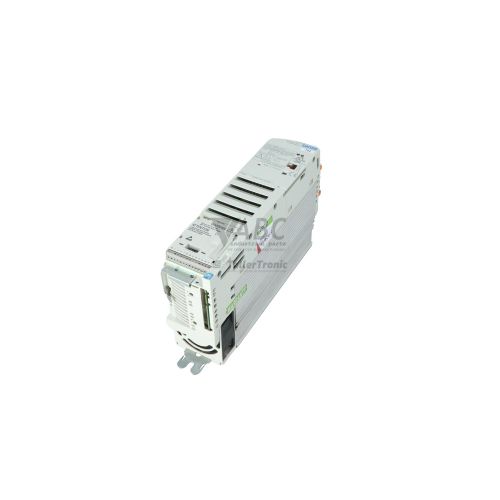
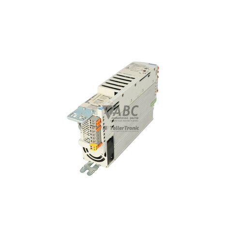
Lenze 13142439 E82EV152_4C 8200 Vector Frequency Inverter 1.5kW


Het item werd toegevoegd aan uw offerteaanvraag
Product Information
The Lenze 13142439 (model designation E82EV152_4C) is a 1.5 kW 3-phase AC frequency inverter within the Lenze 8200 vector product line. Operating across an input voltage range of 320 V AC to 528 V AC at 45 to 65 Hz, this drive supplies a continuous output current of 3.9 A with a 150% maximum overload output current of 5.85 A for up to 60 seconds. Designed with an IP20 protection rating and a coldwall mounting construction, the unit dissipates thermal power loss of 60 W through cabinet heat sinks or mounting surfaces. It supports linear V/f, quadratic V/f, and sensorless vector control methods, operating across an output frequency spectrum from 0 to 480 Hz at an 8 kHz switching frequency.
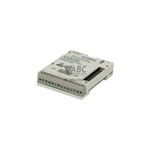
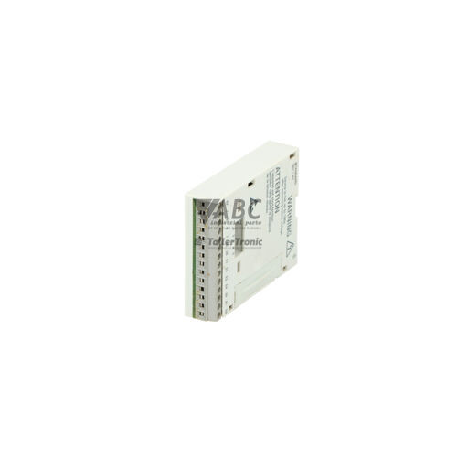
Integration into control architecture relies on a modular setup separating the main power unit from control interfaces. The inverter incorporates an Automation Interface (AIF) slot that accommodates E82ZAF series function modules, including PROFIBUS DP, CANopen, and LECOM options. Commissioning a replacement unit requires configuring parameter settings and aligning installed interface hardware. Parameter data can be cloned directly via the optional plug-in E82ZLCM EEPROM parameter module without requiring a computer or software connection, while advanced parameterization and backup management are supported through Global Drive Control (GDC) software version 4.0 or higher or an optional E82ZBC / EMZ2101 operating keypad. ABC Industrial Parts can assist maintenance teams with donor parameter extraction and replacement drive preparation to simplify machine restoration.
System status and fault conditions are communicated through dual front status LEDs alongside keypad displays and fieldbus diagnostic tools. The red Fault / TRIP LED illuminates solid or flashes during active TRIP states, while the green Operation / Ready LED indicates normal drive operation or readiness. Maintenance personnel can inspect the built-in diagnostic history buffer, which records the last eight TRIP events in parameters C0168/1 through C0168/8, or monitor live status using the GDC diagnostic window. Initial troubleshooting should verify 3-phase mains voltage, motor insulation, fieldbus wiring, and cooling airflow. When internal hardware errors such as code H05 occur on the control board, component replacement or a tested exchange drive from ABC Industrial Parts offers a dependable path to restoring operational availability.
Technical Specifications
| Manufacturer | Lenze |
| Part number | 13142439 |
| Model / Type designation | E82EV152_4C |
| Product family | 8200 vector |
| Component type | Frequency Inverter |
| Rated power | 1.5 kW |
| Supply voltage range | 320 - 528 V AC |
| Rated input current | 3.9 A |
| Continuous output current | 3.9 A |
| Maximum output current (60 s) | 5.85 A |
| Output voltage range | 0 - 400 V AC |
| Output frequency range | 0 - 480 Hz |
| Switching frequency | 8 kHz |
| Control method | V/f linear, V/f quadratic, sensorless vector control |
| Protection rating | IP20 |
| Power loss | 60 W |
Programming and Configuration
The Lenze 8200 vector series utilizes a modular memory architecture centered around the plug-in E82ZLCM EEPROM parameter module. This physical memory chip stores all application-specific parameters, allowing complete configuration transfer between drives during maintenance. In the event of an inverter swap, technicians can insert the configured EEPROM module directly into the replacement E82EV152_4C unit to achieve identical control behavior without executing a manual parameter upload.
Comprehensive programming, tuning, and parameter management can be executed through Global Drive Control (GDC) software version 4.0 or higher. Connecting via LECOM RS232/RS485 adapters or fieldbus connections, GDC provides interactive parameterization, online motor tuning, and real-time trace recording. Alternatively, local setup can be completed using the pluggable E82ZBC or EMZ2101 operating keypad. In instances where configuration memory becomes corrupted, resetting the inverter to default settings via parameter C0002 restores factory baselines for commissioning.
Communication and System Integration
The E82EV152_4C inverter features an integrated Automation Interface (AIF) slot designed to receive pluggable Lenze E82ZAF series function modules. These modules establish fieldbus connectivity across industrial networks, enabling seamless communication with higher-level programmable logic controllers and distributed I/O systems. Supported interface standards include PROFIBUS DP, CANopen, and LECOM serial communication interfaces (RS232 or RS485).
When configured for CANopen or System Bus communications, parameters such as baud rate settings in C0351 and node addressing must match network architecture requirements. Proper physical bus termination, such as 120-ohm terminal resistors across CAN lines, is essential to prevent frame corruption and communication interruptions. The drive continuously monitors module integrity and generates communication diagnostic warnings, such as error code CE0 for AIF slot failures or CE1 for System Bus disconnects.
Diagnostics and Status Indication
Visual monitoring of the Lenze 13142439 is facilitated by front-panel status LEDs and external display accessories. The green Operation / Ready LED signals normal operational status or standby ready state, while the red Fault / TRIP LED flashes or remains lit to indicate an active shutdown condition. For precise troubleshooting, an optional E82ZBC or EMZ2101 keypad displays specific fault codes on its 7-segment or LCD display.
Diagnostic data can also be evaluated remotely using GDC software or fieldbus diagnostic words transmitted to the PLC. The internal memory maintains a dedicated fault buffer across parameters C0168/1 to C0168/8, storing the sequence of the last eight fault conditions. This historical log allows technicians to analyze transient faults, such as momentary line supply drops or overcurrent spikes, even after power cycling.
Status LED Indicators
| LED | Color/Status | Meaning |
|---|---|---|
| Fault / TRIP | Red - Solid / Flashing | Fault or TRIP state detected |
| Operation / Ready | Green - Solid / Flashing | Inverter operating normally or ready for operation |
Replacement and Spare Part Considerations
When replacing an existing Lenze E82EV152_4C frequency inverter, maintaining exact electrical and mechanical specifications is necessary. The unit features an IP20 rated coldwall mounting enclosure, engineered to transfer heat directly through cabinet mounting surfaces. Ensure the mounting space and rear contact surface are free from debris and equipped with adequate thermal pathing to maintain specified 60 W heat dissipation.
Prior to putting a spare unit into operation, verify that the installed AIF communication module matches the original fieldbus network topology, whether PROFIBUS DP, CANopen, or LECOM. Parameter profiles can be transferred instantly by inserting the existing E82ZLCM EEPROM module into the replacement unit. If the memory module is unavailable or unreadable, parameters must be reloaded using Global Drive Control software V4.0+ or manually configured via an E82ZBC or EMZ2101 keypad.
Error Codes & Fault Codes
The following error codes may be displayed during operation or diagnostics:
| Code | Name | Description | Possible Cause | Recommended Action |
|---|---|---|---|---|
| OC1 | Short circuit / Earth fault | Short circuit or short to earth detected on output phase U, V, W. | Short circuit in motor cable or motor winding, capacitive cable length exceeded, inter-turn fault. | Check motor wiring and motor windings for short circuit/earth fault; check cable length and capacitance. |
| OC2 | Earth fault | Earth fault detected on output phase during operation. | Insulation breakdown in motor winding or power cable to earth. | Check motor insulation resistance with megohmmeter; inspect motor connection box and cable. |
| OC5 | Overcurrent during acceleration | Output current limit exceeded during speed acceleration ramp. | Acceleration time (C0012) too short, V/f characteristic set incorrectly, motor stalled or overloaded. | Increase acceleration time C0012; check motor load and V/f configuration. |
| OU | DC bus overvoltage | DC bus voltage exceeded upper threshold level (~770 V DC). | Deceleration time (C0013) too short, generatoric operation without brake module/resistor, supply voltage too high. | Increase deceleration time C0013; connect optional brake module/resistor; verify mains voltage. |
| LU | DC bus undervoltage | DC bus voltage fell below lower threshold level (~400 V DC on 400V class). | Mains supply voltage drop, phase failure, blown line fuse, power supply interruption. | Check input mains line voltage, fuses, and line switch/contactor. |
| OH | Heatsink overtemperature | Power section heatsink temperature exceeded maximum limit (>90 °C). | Cooling fan blocked or failed, insufficient cabinet ventilation, ambient temperature too high, heavy continuous overload. | Clean heatsink fins, check cabinet ventilation, ensure fan operation, lower switching frequency (C0018). |
| OH4 | Motor overtemperature | Motor PTC / thermal contact connected to terminals T1/T2 triggered. | Motor thermal overload, fan failure on motor, open circuit at PTC terminals. | Allow motor to cool; check motor load; check PTC/TKO wire connection at T1/T2 terminals. |
| OH7 | Internal overtemperature | Internal air temperature inside the inverter enclosure exceeded safe threshold. | Ambient temperature inside control cabinet too high. | Improve cooling inside control cabinet; check internal airflow. |
| LP1 | Mains phase failure | One phase of the 3-phase AC input supply missing during operation. | Blown input fuse, loose wire terminal on input supply L1/L2/L3. | Check input wiring and supply line fuses under load. |
| CE0 | AIF communication error | Communication failure between inverter control board and Function Module in AIF slot. | Loose function module, fieldbus disconnection, corrupted AIF frame. | Re-seat function module; check fieldbus connection and bus wiring. |
| CE1 | System Bus (CAN) communication error | CANbus error or bus-off condition on System Bus interface. | CAN cable disconnected, missing terminating resistor, incorrect baud rate or node address. | Check CAN line wiring, 120 ohm terminal resistors, baud rate settings in C0351. |
| EEr | External TRIP error | External fault triggered via digital input assigned to TRIP function. | External monitoring device (safety relay, pressure switch, external sensor) tripped. | Inspect external fault circuit connected to configured digital input terminal. |
| H05 | Internal hardware failure | Internal micro-controller or memory hardware defect detected. | Internal board component failure or internal power supply fault. | Internal hardware fault — return unit for repair or replace inverter. |
| Pr1 | Parameter set error | Corrupted parameter memory or parameter set mismatch during load. | Power failure during parameter save, incomplete transfer. | Reset inverter to factory default settings via C0002 and re-commission parameters. |
| NMAX | Maximum speed limit exceeded | Actual motor speed exceeded maximum configured frequency (C0032) by more than 20%. | Incorrect speed feedback settings, over-hauling motor load. | Check drive configuration C0032, check slip compensation, check motor load. |
Frequently Asked Questions
How can parameter settings be transferred to a replacement Lenze E82EV152_4C inverter?
Parameter settings can be transferred by moving the plug-in E82ZLCM EEPROM parameter module from the original drive to the replacement unit. Alternatively, parameters can be uploaded and restored using Global Drive Control (GDC) software version 4.0 or higher, or configured manually using an E82ZBC or EMZ2101 operating keypad.
What fieldbus communication options are supported by the E82EV152_4C?
The E82EV152_4C includes an Automation Interface (AIF) slot that accepts Lenze E82ZAF series function modules. These modules enable integration with PROFIBUS DP, CANopen, and LECOM RS232/RS485 networks.
What do the status LEDs on the front panel indicate?
The green Operation / Ready LED indicates that the drive is operating normally or ready for operation. The red Fault / TRIP LED illuminates solid or flashes when a fault or TRIP state is detected.
What action should be taken if fault code H05 appears?
Fault code H05 indicates an internal micro-controller or memory hardware defect. Because internal hardware failures are board-level defects, the inverter must be returned for repair or replaced.
Take advantage of our exchange formula
A defective product does not have to be worthless. At ABC Industrial Parts, you can hand in defective products and immediately benefit from a discount on your new purchase. This is a smart way to save money while contributing to a circular economy.
Play it safe with our warranty conditions
Industrial plants prefer to keep running invariably, no matter what. Therefore, it is essential that you can rely on high-quality products and/or sustainable repairs. With our warranty conditions, you can count on certainty, whether you choose new, used or repaired products.
Data backup and recovery
Have you lost valuable parameters or data due to a malfunction while the manufacturer no longer provides support? At ABC Industrial Parts, we help you secure this data, both for common and specific products.
Specific firmware and hardware versions
If you are working with specific hardware or firmware versions that are no longer available from the manufacturer, ABC Industrial Parts is your partner. When making your enquiry, clearly state which versions you need, we will then look at the possibilities of supplying those versions, so that your installations continue to function optimally.
Disclaimer:
We are not an authorised distributor of Lenze.
Product photos are for illustration purposes only and may differ from the actual product delivered.
Some of the content on this page was created with the help of AI. While we strive to provide accurate and up-to-date information, errors may occur.