Lenze 13445379 ECSEP004C4B ECS Power Supply Module 4.8kW



Het item werd toegevoegd aan uw offerteaanvraag
Product Information
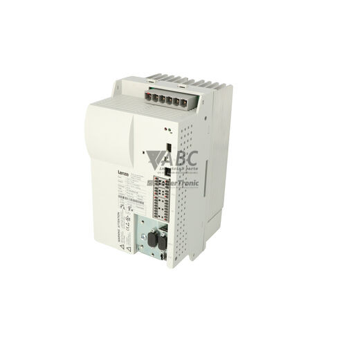
The Lenze 13445379, model ECSEP004C4B, is a central power supply module within the Lenze ECS family designed to power multi-axis servo drive architectures. Operating across a 3-phase AC input range of 320 V AC to 528 V AC (nominal 3x 400 V AC or 480 V AC at 48 to 62 Hz), this unit converts incoming mains power into a regulated intermediate DC bus voltage between 565 V DC and 675 V DC. It provides a continuous DC power output of 4.8 kW with a rated continuous output current of 9.6 A and an input current rating of 8 A. To accommodate high transient loads during acceleration spikes, the module delivers up to 12 kW of peak output power and a 24 A peak output current. An integrated brake chopper circuit is built into the module to handle energy generated during motor deceleration cycles.
Connecting the ECSEP004C4B into a multi-axis arrangement involves high-voltage DC bus links (+UG and -UG), 3-phase mains connections at terminal X1, ready contact connections at terminal X6, and connections for an external braking resistor. System configuration and parameterization are managed using hardware DIP switches on the unit for fast voltage threshold setup, or digitally through engineering software tools such as Lenze Global Drive Control (GDC) and EASY Starter connected via Lenze USB-to-CAN adapters (EMF2177IB or EMB9251). Commissioning a replacement unit requires verifying that all hardware DIP switch positions match the original configuration and that diagnostic parameters align with downstream axis modules, such as the Lenze ECSEA, ECSEM, or ECSED series. Technical guidance for parameter verification or spare unit preparation is available through ABC Industrial Parts.
Diagnostic information is available directly on the front panel via status LEDs, where a green Ready LED indicates normal DC bus operation and a red Error LED signals system faults such as overvoltage, undervoltage, overtemperature, or ground faults. External status monitoring is supported by the ready contact relay output at terminal X6 and real-time CAN bus diagnostic registers. Initial troubleshooting should include measuring 3-phase line voltage at terminal X1, checking line fuses, inspecting external brake resistor resistance, and testing DC bus insulation integrity. When hardware fault codes such as H05 or internal memory faults like EER occur alongside a solid red error LED, internal board-level failures are present that cannot be serviced in the field, making a tested replacement or repair through ABC Industrial Parts the recommended solution.
Technical Specifications
| Manufacturer | Lenze |
| Part Number | 13445379 |
| Model / Type | ECSEP004C4B |
| Product Family | ECS |
| Component Type | Power Supply Module |
| Rated Power Output | 4.8 kW |
| Peak Power Output | 12 kW |
| Supply Voltage (Nominal) | 3x 400 / 480 V AC |
| Supply Voltage Range | 320 - 528 V AC |
| Mains Frequency | 48 - 62 Hz |
| Rated Input Current | 8 A |
| DC Output Voltage | 565 - 675 V DC |
| Continuous Output Current | 9.6 A |
| Peak Output Current | 24 A |
| Brake Chopper | Integrated |
Programming and Configuration
The Lenze 13445379 ECSEP004C4B power supply module utilizes both hardware-based controls and software interfaces for setup and operational parameterization. Integrated DIP switches located on the module permit immediate hardware-level adjustments for DC bus voltage thresholds without requiring software equipment during basic installation.
For complete parameter access and active system monitoring, the module interfaces with Lenze Global Drive Control (GDC) or EASY Starter engineering environments. Connection to PC tools is established using a Lenze USB-to-CAN adapter, such as model EMF2177IB or EMB9251. This software link enables field personnel to read diagnostic registers, modify operational limits, and ensure full configuration alignment with downstream ECS series axis modules.
Communication and System Integration
The ECSEP004C4B power supply features a built-in CAN system bus interface capable of communication speeds up to 500 kbit/s. This integrated network link enables real-time data exchange with higher-level plant controllers and supervisory systems, facilitating direct monitoring of DC bus health and diagnostic status.
Proper physical network implementation requires standard shielded CAN cabling and a 120-ohm bus termination resistor installed at each physical end of the bus line. Diagnostic parameters sent across the system bus allow PLC control systems to monitor operational readiness and react immediately to power supply status changes.
Diagnostics and Status Indication
Operational status and fault conditions on the Lenze 13445379 ECSEP004C4B are evaluated using front-panel LED indicators, the digital ready contact output at terminal X6, and CAN bus diagnostic registers. The front panel LEDs provide clear visual feedback regarding power availability and operational readiness.
The output relay at terminal X6 provides a hardware signal to higher-level safety circuits or control systems, opening its contact when the module detects a fault or when DC bus levels fall outside the permitted operating range.
Status LED Indicators
| LED | Color/Status | Meaning |
|---|---|---|
| Ready (Green) | Green - Solid | Lit continuous when DC bus voltage is in normal operating range and power supply is ready for operation. |
| Error (Red) | Red - Solid or Flashing | Lit or blinking when a fault condition is detected (e.g., overvoltage, undervoltage, overtemperature, ground fault). A continuous solid red light or hardware fault signal indicates an internal board-level failure requiring repair or replacement. |
Replacement and Spare Part Considerations
When replacing a Lenze 13445379 ECSEP004C4B power supply module, verify that the replacement part number and model number match existing cabinet specifications to ensure full mechanical and electrical compatibility with connected Lenze ECS series axis modules (ECSEA, ECSEM, ECSED). Prior to applying power, set the hardware DIP switches on the new module to match the original configuration.
Inspect all input lines at terminal X1, DC bus connections (+UG and -UG), and external braking resistor cabling for proper torque and insulation integrity. Ensure CAN bus cabling is securely fastened, baud rates match plant specifications, and 120-ohm termination resistors are properly situated at network endpoints before putting the spare unit back into active service.
Error Codes & Fault Codes
The following error codes may be displayed during operation or diagnostics:
| Code | Name | Description | Possible Cause | Recommended Action |
|---|---|---|---|---|
| OU | DC Bus Overvoltage | DC bus voltage exceeded upper protection threshold (>770 V DC for 400 V supply / >800 V DC for 480 V supply). | Regenerative braking energy exceeds brake chopper capacity, external brake resistor open-circuit, or incorrect resistance value. | Check external brake resistor resistance and connection; increase deceleration times on connected drive axes. |
| LU | DC Bus Undervoltage | DC bus voltage dropped below minimum threshold (<285 V DC or <430 V DC). | Mains voltage failure, input phase missing, line fuse blown, or heavy line voltage sag. | Measure 3-phase mains supply voltage at input terminal X1; check fuses and circuit breakers. |
| OH | Heatsink Overtemperature | Power module heatsink temperature exceeded allowable operating limit. | Inadequate cabinet cooling, fan failure, blocked airflow, or prolonged thermal overload. | Check control cabinet ventilation and ambient temperature; inspect module cooling fan and clean heatsink fins. |
| OC1 | Overcurrent / Short Circuit | Instantaneous overcurrent or short circuit detected on DC bus or brake resistor output. | Short circuit in DC bus wiring (+UG / -UG), brake resistor short circuit to ground, or damaged power stage in connected axis module. | Disconnect power and check DC bus cabling and brake resistor insulation. Disconnect axis modules individually to isolate fault. |
| PE | Earth Fault | Ground fault detected in power supply unit or connected DC bus circuit. | Insulation breakdown to earth/ground in DC bus cabling, brake resistor, or connected motor/drive modules. | Test ground insulation resistance on DC bus lines and connected load components. |
| CE0 | CAN Communication Error | System bus (CAN) communication error or line interruption. | Loose CAN connector, missing 120-ohm bus termination resistor, baud rate mismatch, or high electromagnetic interference. | Inspect CAN cabling, verify bus termination resistors at both line ends, and check shielding and grounding. |
| EER | EEPROM Fault | Internal memory checksum or data write error. | Internal EEPROM memory corruption or component degradation. | Internal hardware fault — perform power cycle, reset module parameters to default, or return unit for factory repair. |
| H05 | Hardware Fault | Internal power board or gate drive fault. | Defective internal power electronic hardware or board component failure. | Internal hardware fault — return unit for repair or replace power supply module. |
Frequently Asked Questions
Which software tools are used to configure the Lenze 13445379 ECSEP004C4B?
Configuration and diagnostic monitoring are performed using Lenze Global Drive Control (GDC) or Lenze EASY Starter software, connecting via a Lenze USB-to-CAN adapter such as the EMF2177IB or EMB9251.
What causes fault code OU on the ECSEP004C4B unit?
Fault code OU indicates a DC bus overvoltage exceeding 770 V DC on a 400 V supply or 800 V DC on a 480 V supply. This occurs when regenerative braking energy exceeds the brake chopper capacity or when the external brake resistor is open-circuit or incorrect in resistance value.
Can hardware settings be adjusted without connecting software?
Yes, the ECSEP004C4B features hardware DIP switches directly on the module that allow manual adjustments for voltage thresholds without software.
What does a solid red Error LED indicate on the module?
A solid red Error LED or fault code H05 indicates an internal power electronic or gate drive failure on the circuit board, which requires module repair or replacement.
Which drive modules are compatible with this power supply?
The ECSEP004C4B power supply module is designed to energize Lenze ECS series multi-axis drive modules, including ECSEA, ECSEM, and ECSED axis units.
Take advantage of our exchange formula
A defective product does not have to be worthless. At ABC Industrial Parts, you can hand in defective products and immediately benefit from a discount on your new purchase. This is a smart way to save money while contributing to a circular economy.
Play it safe with our warranty conditions
Industrial plants prefer to keep running invariably, no matter what. Therefore, it is essential that you can rely on high-quality products and/or sustainable repairs. With our warranty conditions, you can count on certainty, whether you choose new, used or repaired products.
Data backup and recovery
Have you lost valuable parameters or data due to a malfunction while the manufacturer no longer provides support? At ABC Industrial Parts, we help you secure this data, both for common and specific products.
Specific firmware and hardware versions
If you are working with specific hardware or firmware versions that are no longer available from the manufacturer, ABC Industrial Parts is your partner. When making your enquiry, clearly state which versions you need, we will then look at the possibilities of supplying those versions, so that your installations continue to function optimally.
Disclaimer:
We are not an authorised distributor of Lenze.
Product photos are for illustration purposes only and may differ from the actual product delivered.
Some of the content on this page was created with the help of AI. While we strive to provide accurate and up-to-date information, errors may occur.