Lenze 324514 764.E1 – Serie 760 3kW Frequency Inverter


Het item werd toegevoegd aan uw offerteaanvraag
Product Information
The Lenze 324514 (model 764.E1) is a 3.0 kW AC frequency inverter from the Lenze Serie 760 family, engineered for precise speed regulation and dynamic control of three-phase asynchronous motor drives. Operating on a three-phase mains supply from 380 V AC to 460 V AC, this industrial drive provides a rated output current of 7.3 A at 400 V AC across an output frequency range of 0 to 480 Hz. Control is executed through V/f characteristic management with integrated slip compensation to maintain motor torque and speed consistency under fluctuating mechanical loads. Designed for cabinet enclosure mounting with an IP20 protection rating, the unit features integrated screw terminal block connections for setpoint analog inputs, programmable digital logic inputs, and a dedicated fault relay output contact.
Integrating a replacement unit into an existing control cabinet requires matching physical connections and transferring operational settings. The 764.E1 drive utilizes non-volatile EEPROM parameter storage to retain operational parameters during power outages. Commissioning a spare unit or adjusting operational profiles is performed using the detachable Operating Module Keypad 2102 or via PC software using Lenze Global Drive Control (GDC). When swapping drives in the field, parameter profiles can be copied directly from the original keypad module or uploaded via software to ensure correct acceleration ramps, output current limits, and fieldbus communication settings. Expert support from ABC Industrial Parts helps technicians quickly identify compatible spare drives and parameter tools to minimize system downtime.
Real-time diagnostic feedback and fault detection on the Lenze 324514 are handled through front status LED indicators and detailed trip messaging. Three front panel LEDs provide status indication for readiness, active TRIP faults, and current limit warnings. Detailed fault codes, including short circuit events (OC1), overcurrent ramps (OC2/OC3/OC4), DC bus overvoltage (OU), undervoltage (LU), or heatsink overtemperature (OH), are displayed on the plug-in keypad 2102 or via serial LECOM registers. First-line troubleshooting should include testing mains supply voltages on terminals L1, L2, and L3, verifying motor winding insulation, and checking panel ventilation fans. For hardware issues such as internal EEPROM checksum failures or power stage defects, replacement or testing through ABC Industrial Parts provides a reliable path back to full production.
Technical Specifications
| Manufacturer | Lenze |
| Part Number | 324514 |
| Model / Type | 764.E1 |
| Product Family | Serie 760 |
| Component Type | Frequency Inverter |
| Rated Power | 3.0 kW |
| Supply Voltage Range | 380 - 460 V AC |
| Rated Output Current | 7.3 A |
| Output Voltage | 400 V AC |
| Output Frequency Range | 0 - 480 Hz |
| Control Principle | V/f characteristic control with slip compensation |
| Protection Rating | IP20 |
Programming and Configuration
Parameter entry and operational setup on the Lenze 324514 frequency inverter are supported through the optional plug-in Operating Module Keypad 2102 or by connecting a PC running Lenze Global Drive Control (GDC) software. Keypad 2102 allows direct entry of motor parameter structures, including acceleration time ramps, deceleration times, current limits, and maximum output frequencies.
All parameter data set on the drive is written directly to non-volatile EEPROM parameter storage within the internal board memory, ensuring zero data loss when power is removed. When commissioning a replacement drive, parameter sets saved on the keypad module or stored as GDC project files can be downloaded directly into the spare unit, restoring exact operational routines without manual recalculation.
Communication and System Integration
The modular hardware design of the Lenze Serie 760 enables communication options to match fieldbus requirements. Primary field wiring is attached via integrated screw terminals for setpoint analog voltage or current signals, programmable digital inputs, and a hardware trip relay output contact.
Network connectivity and remote diagnostic capabilities are expanded by fitting optional communication module cards. The drive supports Lenze LECOM communication modules (models 2102 and 2111) for RS232 or RS485 serial communication, as well as PROFIBUS-DP adapter modules (models 2131 and 2133), enabling seamless integration into centralized PLC architectures.
Diagnostics and Status Indication
Operational status and fault identification on the Lenze 324514 inverter are indicated visually through front-facing LEDs. A solid green LED indicates that the drive is powered and ready for operation, a solid yellow LED warns that the drive has reached its current limit, and a solid red LED alerts operators to an active TRIP fault condition.
Detailed diagnostic information can be extracted using the 2102 operating keypad or through PC monitoring via Lenze Global Drive Control (GDC) software. In addition, serial register interrogation via LECOM modules and automatic switching of the internal fault relay contact allow higher-level automation systems to react immediately to drive trip conditions.
Status LED Indicators
| LED | Color/Status | Meaning |
|---|---|---|
| Ready / Operation | Green - Solid | Inverter in operation / Ready |
| TRIP Fault | Red - Solid | TRIP fault active |
| Current Limit / Warning | Yellow - Solid | Current limit reached / Warning |
Replacement and Spare Part Considerations
Replacing an existing Lenze 324514 drive requires verifying that the replacement unit shares the exact 764.E1 model identifier and 3.0 kW power specification. Matching the power rating ensures that input line fusing, cable cross-sections, and cabinet cooling remain compatible without structural modifications.
Before applying power to a replacement unit, transfer all optional hardware cards—such as LECOM or PROFIBUS communication modules—from the original unit. Once installed, restore parameter data using either the 2102 operating keypad transfer function or Lenze Global Drive Control software to configure motor characteristics, deceleration ramps, and bus addresses to match machine specifications.
Error Codes & Fault Codes
The following error codes may be displayed during operation or diagnostics:
| Code | Name | Description | Possible Cause | Recommended Action |
|---|---|---|---|---|
| OC1 | Short Circuit / Earth Fault | Short circuit on motor terminals or earth fault in motor cabling/windings. | Short circuit on output phases, defective motor cable, earth fault, internal inverter power stage short. | Check motor wiring and insulation, test motor for winding shorts, check inverter power stage. |
| OC2 | Overcurrent during Acceleration | Output current exceeds threshold during acceleration ramp. | Acceleration time ramp set too short, motor mechanically blocked, motor rating incorrectly configured. | Increase acceleration time (Ti), check motor load for mechanical binding, verify motor parameters. |
| OC3 | Overcurrent during Deceleration | Output current exceeds threshold during deceleration ramp. | Deceleration time ramp set too short, high load inertia. | Increase deceleration time (Td) or install a braking resistor module. |
| OC4 | Overcurrent during Constant Speed / Overload | Inverter output current exceeds maximum limit during steady-state operation. | Sudden load impulse, motor stall, mechanical overload. | Reduce load, check machine mechanics for jams. |
| OU | DC Bus Overvoltage | DC bus voltage exceeded upper threshold limit. | Regenerative energy from decelerating heavy load, deceleration ramp too short, mains voltage spike. | Extend deceleration time, fit dynamic braking resistor option, check mains voltage. |
| LU | DC Bus Undervoltage | DC link voltage dropped below lower operation threshold. | Mains supply failure, voltage dip, blown input fuse, phase loss. | Check main power supply, check line fuses and supply wiring. |
| OH | Inverter Heatsink Overtemperature | Heatsink temperature exceeded maximum allowable limit. | Inadequate cabinet cooling, cooling fan failure, dirty heatsink fins, excessive ambient temperature. | Clean heatsink fins, verify control cabinet cooling fan and airflow, ensure ambient temperature is within specifications. |
| OH4 | Motor Overtemperature | Motor temperature sensor trip (PTC sensor triggered). | Motor thermal overload, cooling fan failure on motor, defective PTC connection. | Allow motor to cool, check motor loading, verify forced-cooling fan on motor. |
| OL | Ixt Motor / Inverter Overload | Ixt overload integrator threshold exceeded. | Continuous operation above rated current limit. | Reduce continuous load on motor, verify drive dimensioning. |
| EE | EEPROM Fault | Checksum failure or corruption detected in internal parameter storage EEPROM. | Internal hardware failure, power loss during parameter save operation. | Re-initialize parameters to factory default. If error persists, internal board failure requiring unit replacement. |
| CE / CE0 | LECOM Communication Error | Loss of communication via serial LECOM interface module. | Broken communication cable, module disconnected, parameter timeout. | Check LECOM wiring, verify baud rate and address settings, inspect communication module seat. |
| LP | Phase Failure | Mains supply input phase failure detected. | Loose mains terminal, blown line fuse on one phase. | Check 3-phase mains voltage at input terminals L1, L2, L3. |
Frequently Asked Questions
How do I transfer parameters to a new Lenze 324514 drive?
Parameters stored in the non-volatile EEPROM can be saved to a detachable Operating Module Keypad 2102 and copied to the replacement drive, or uploaded and downloaded using Lenze Global Drive Control (GDC) software on a PC.
What fieldbus protocols are supported by the 764.E1 inverter?
The Lenze 764.E1 inverter supports LECOM serial interfaces (RS232/RS485) via modules 2102/2111 and PROFIBUS-DP connectivity via option modules 2131/2133.
What does a solid yellow LED indicate on the front panel?
A solid yellow LED indicates a current limit warning condition, signaling that the inverter has reached its configured maximum output current threshold.
How should an EE fault code be resolved?
An EE fault indicates an EEPROM checksum error. Attempt to re-initialize parameters to factory default settings. If the fault does not clear, an internal board failure has occurred requiring drive replacement.
What are the mains supply requirements for the Lenze 324514?
The inverter requires a three-phase AC input supply rated between 380 V AC and 460 V AC, delivering up to 7.3 A continuous output current at 400 V AC.
Take advantage of our exchange formula
A defective product does not have to be worthless. At ABC Industrial Parts, you can hand in defective products and immediately benefit from a discount on your new purchase. This is a smart way to save money while contributing to a circular economy.
Play it safe with our warranty conditions
Industrial plants prefer to keep running invariably, no matter what. Therefore, it is essential that you can rely on high-quality products and/or sustainable repairs. With our warranty conditions, you can count on certainty, whether you choose new, used or repaired products.
Data backup and recovery
Have you lost valuable parameters or data due to a malfunction while the manufacturer no longer provides support? At ABC Industrial Parts, we help you secure this data, both for common and specific products.
Specific firmware and hardware versions
If you are working with specific hardware or firmware versions that are no longer available from the manufacturer, ABC Industrial Parts is your partner. When making your enquiry, clearly state which versions you need, we will then look at the possibilities of supplying those versions, so that your installations continue to function optimally.
Disclaimer:
We are not an authorised distributor of Lenze.
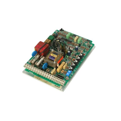
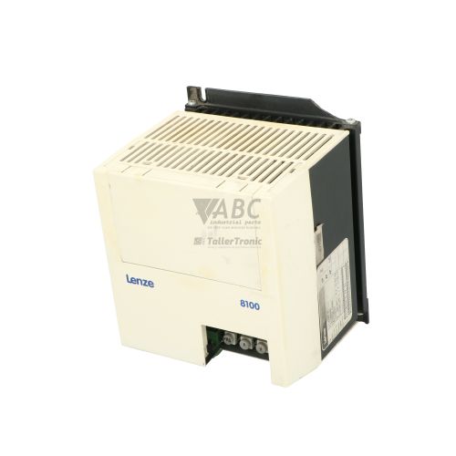
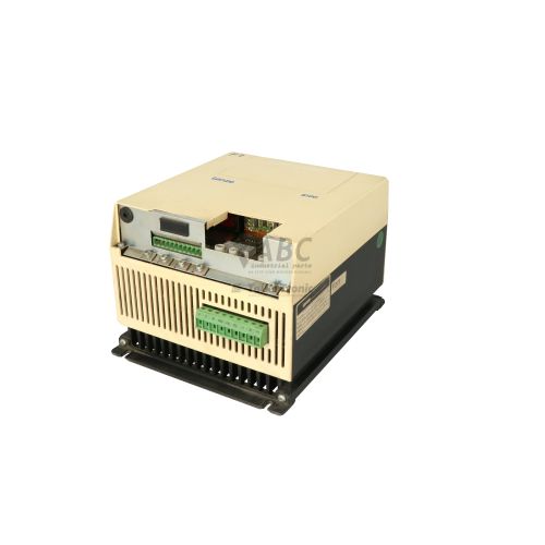
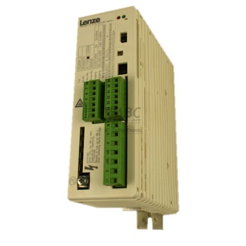
Product photos are for illustration purposes only and may differ from the actual product delivered.
Some of the content on this page was created with the help of AI. While we strive to provide accurate and up-to-date information, errors may occur.