Lenze 761E.6 Servo Drive – 760 Series 2.7kW 6A Positioning Controller



Het item werd toegevoegd aan uw offerteaanvraag
Product Information
The Lenze 761E.6 is a digital servo drive and integrated positioning controller from the Lenze 760 product family designed for precise motion control of brushless AC servo motors with resolver feedback. Powered by a 3-phase supply rating of 380 V AC to 460 V AC (operational from 342 V AC to 506 V AC), this unit delivers a continuous output current of 6.0 A with a rated power output of 2.7 kW. For dynamic acceleration cycles in high-performance machinery, the drive delivers up to 200% peak output current of 12.0 A for 5 seconds at an 8 kHz switching frequency.
Interfacing with external automation systems is handled through 6 digital inputs, 4 digital outputs, 2 differential analog inputs, and connector X6 for resolver feedback. Fieldbus network integration and local parameter management are supported via a modular expansion slot that accepts optional modules including the 2102 IB operating keypad, 2111 IB RS232 module, 2131 IB PROFIBUS-DP module, 2133 IB CANopen module, and 2138 IB INTERBUS module. Placing a spare unit into service requires matching parameter sets, which can be configured via Lenze Global Drive Control (GDC) software or copied directly using the 2102 IB keypad. Non-volatile internal EEPROM storage permits parameter extraction from a donor unit to minimize machine commissioning time, with technical assistance available from ABC Industrial Parts for backup transfer.
Real-time operational feedback is indicated by on-board LED diagnostics, where a solid green DRIVE READY LED signals controller readiness and a solid red TRIP / FAULT LED alerts operators to a protective trip. Fault codes and status history are logged in diagnostic registers C0168 and C0170, accessible through the 2102 IB keypad or GDC software. First-line troubleshooting involves checking mains supply stability, motor cable insulation, resolver shielding on connector X6, and parameter limits such as overspeed setting C0596. Hardware failures involving internal sensors or power stages cannot be serviced in the field, making a pre-tested replacement unit from ABC Industrial Parts the recommended solution to restore production quickly.
Technical Specifications
| Manufacturer | Lenze |
| Part Number | 761E.6 |
| Component Type | Servo Drive |
| Product Family | Lenze 760 |
| Rated Power | 2.7 kW |
| Supply Voltage Range | 380 - 460 V AC |
| Supply Voltage Min / Max | 342 - 506 V AC |
| Continuous Output Current | 6.0 A |
| Peak Output Current | 12.0 A (up to 5 s) |
| Output Voltage | 0 - Mains Voltage V AC |
| Switching Frequency | 8 kHz |
| Digital Inputs | 6 |
| Digital Outputs | 4 |
| Analog Inputs | 2 (Differential) |
| Feedback System | Resolver feedback |
Programming and Configuration
Parameter setting and drive configuration for the Lenze 761E.6 are managed through Lenze Global Drive Control (GDC) PC software or locally using the plug-in 2102 IB operating keypad module. Operational parameters, speed loop gain settings, positioning tasks, and motor feedback profiles are retained in dual non-volatile EEPROM memory spaces. This dual parameter memory architecture ensures data retention during power interruption and enables reliable cloning across identical replacement hardware.
When commissioning a replacement drive, software parameter integrity must be confirmed before enabling the output stage. Uploading parameter sets with rating mismatches triggers trip code EEr, while non-volatile memory corruption generates code EE0. Engineers must ensure parameter files match the 2.7 kW drive rating and perform a parameter reload or factory reset if memory corruption occurs.
Communication and System Integration
The Lenze 761E.6 servo drive includes integrated hardware terminal connections alongside a modular communication slot designed for host system integration. Control architectures can interface via standard digital I/O lines (6 inputs, 4 outputs) and 2 differential analog inputs, while resolver feedback wiring connects directly to dedicated interface connector X6.
Network integration into broader control architectures is achieved by fitting the modular expansion slot with optional fieldbus interface modules. Supported protocols include CANopen via the 2133 IB module, PROFIBUS-DP via the 2131 IB module, INTERBUS via the 2138 IB module, and LECOM serial RS232/RS485 via the 2111 IB or 2112 IB modules. When operating on a CAN bus network, proper bus topology must be maintained with 120-ohm termination resistors fitted at the physical ends of the line to prevent communication interference (code CE1).
Diagnostics and Status Indication
Operational readiness and fault conditions on the Lenze 761E.6 are displayed visually via front-panel LEDs and numeric status codes on the optional 2102 IB keypad. Green LED illumination indicates that drive power is applied and the controller is enabled, whereas a solid red illumination indicates a protective trip state.
Detailed fault analysis is supported by the error history log maintained within diagnostic registers C0168 and C0170. These registers can be interrogated via GDC software or the 2102 IB keypad to evaluate historical trip codes, enabling field engineers to differentiate between external wiring issues and internal hardware faults.
Status LED Indicators
| LED | Color/Status | Meaning |
|---|---|---|
| DRIVE READY | Green - Solid | Drive power is on and controller is enabled/ready |
| TRIP / FAULT | Red - Solid | Protective trip or fault condition has occurred |
Replacement and Spare Part Considerations
When replacing an operational Lenze 761E.6 servo drive, the replacement unit must match the exact part number to ensure power output compatibility (2.7 kW power, 6.0 A continuous output). Using identical hardware avoids control cabinet modifications and maintains physical terminal alignment across input power, motor output, and control I/O.
Commissioning a replacement requires transferring any installed fieldbus communication module (such as the 2131 IB PROFIBUS or 2133 IB CANopen card) from the old unit to the spare drive. Parameter configurations stored in non-volatile memory should be transferred via the 2102 IB keypad or uploaded through Global Drive Control software. Verified replacement units and technical assistance with parameter transfers can be sourced through ABC Industrial Parts.
Error Codes & Fault Codes
The following error codes may be displayed during operation or diagnostics:
| Code | Name | Description | Possible Cause | Recommended Action |
|---|---|---|---|---|
| OC1 | Short Circuit / Overcurrent | Short circuit on output terminals or power stage overcurrent detected | Motor cable short circuit, motor winding ground fault, acceleration ramp too fast, or defective IGBT output stage | Inspect motor cabling and insulation; test motor windings; check acceleration parameter settings. If error persists without motor attached, internal power stage failure occurred (replace unit). |
| OC5 | Earth Fault | Ground fault detected on motor connection cables or internal power stage | Motor phase cable shorted to earth ground or motor insulation breakdown | Check motor leads and junction box for ground shorts; measure motor insulation resistance. |
| OU | Overvoltage DC Bus | DC bus circuit voltage exceeds upper threshold limit | Excessive regenerative energy during deceleration, brake chopper resistor disconnected or defective, mains input voltage too high | Increase deceleration time ramp; verify braking resistor connection and resistance value; check mains supply voltage. |
| LU | Undervoltage DC Bus | DC bus circuit voltage fell below minimum allowable threshold | Mains supply failure, phase loss, input line voltage too low, or internal DC bus pre-charge circuit fault | Check supply voltage and line fuses; verify power connections. If mains voltage is correct, internal supply circuit is damaged requiring service. |
| OH | Heatsink Overtemperature | Inverter heatsink temperature exceeds maximum safety limit | Insufficient cooling, fan failure, ambient temperature too high, dirty heatsink cooling fins, or severe continuous overload | Clean heatsink cooling fins; verify enclosure fan operation; reduce ambient temperature or drive load. |
| OH4 | Motor Overtemperature | Motor thermal sensor / PTC switch opened due to motor overheating | Motor thermal overload, mechanical blockage, or defective motor temperature sensor cable | Allow motor to cool down; inspect mechanical load for binding; check motor thermal sensor wiring. |
| OH7 | Internal Temperature High | Internal electronic component temperature threshold exceeded | Control cabinet cooling failure, excessive internal heat build-up | Improve enclosure ventilation and check cabinet internal fan. |
| OH8 | Heatsink Sensor Fault | Internal temperature sensor on heatsink broken or short-circuited | Hardware failure of temperature measuring circuit | Internal hardware fault — return unit for repair or replace drive. |
| EE0 | EEPROM Checksum Error | Non-volatile parameter memory checksum corruption | Power failure during save, strong electromagnetic interference, or EEPROM chip hardware degradation | Perform factory reset and reload saved parameter set. If fault persists, internal EEPROM hardware failure (return for repair or replace). |
| EEr | Parameter Fault | Invalid parameter set data or parameter range mismatch | Incompatible parameter set uploaded to drive | Reload valid parameter configuration matching drive power rating. |
| Sd | Resolver / Speed Feedback Error | Resolver signal loss, wiring fault, or feedback monitoring trip | Broken resolver cable, shield connection problem, damaged resolver, or incorrect resolver pole-pair setting | Inspect resolver cable and connector X6; check shielding and grounding; test resolver windings. |
| CE0 | LECOM Communication Fault | Communication timeout on serial LECOM interface | Loose cable, baud rate mismatch, host PLC failure, or defective communication module 2111 IB / 2112 IB | Check communication cable, baud rate, and LECOM timeout parameter settings. |
| CE1 | System Bus / CAN Error | CANbus communication disturbance or bus-off condition | Bus cable disconnected, incorrect bus termination resistor, noise interference | Verify CAN shielding, wiring topology, and 120-ohm termination resistors at physical ends of the network. |
| H05 | Internal Hardware Error | Control board self-test failed | Internal electronic board failure or micro-controller malfunction | Internal hardware fault — power cycle drive; if fault persists, return unit for repair or replace drive. |
| NMAX | Overspeed Trip | Actual motor speed exceeded configured maximum speed limit (NMAX) | Speed loop instability, wrong resolver pole pair setting, uncalibrated offset angle, or mechanical overspeed drive by external load | Verify speed loop gain parameters, feedback resolution/poles, and overspeed setting in parameter C0596. |
Frequently Asked Questions
How do I transfer parameters from a failed Lenze 761E.6 to a replacement drive?
Parameter sets can be copied directly using the plug-in 2102 IB operating keypad or uploaded/downloaded via a PC running Lenze Global Drive Control (GDC) software connected through a 2111 IB or 2112 IB LECOM module.
What type of motor feedback is required for the Lenze 761E.6?
The Lenze 761E.6 is designed specifically for brushless AC servo motors equipped with resolver feedback, connecting directly via interface connector X6.
Which communication protocols are supported on the Lenze 761E.6?
The drive accepts plug-in expansion modules for CANopen (2133 IB), PROFIBUS-DP (2131 IB), INTERBUS (2138 IB), and LECOM RS232/RS485 (2111 IB / 2112 IB).
What action should be taken when fault code OC1 appears?
Disconnect the motor leads and inspect the cabling and motor windings for short circuits or ground faults. If code OC1 persists after cycling power with the motor disconnected, an internal IGBT power stage failure has occurred and the drive must be repaired or replaced.
What causes error code Sd on the drive display?
Error Sd indicates a resolver speed feedback fault. Check the wiring and shield connection on connector X6, verify resolver winding continuity, and ensure parameter settings match the motor's resolver pole-pair count.
Take advantage of our exchange formula
A defective product does not have to be worthless. At ABC Industrial Parts, you can hand in defective products and immediately benefit from a discount on your new purchase. This is a smart way to save money while contributing to a circular economy.
Play it safe with our warranty conditions
Industrial plants prefer to keep running invariably, no matter what. Therefore, it is essential that you can rely on high-quality products and/or sustainable repairs. With our warranty conditions, you can count on certainty, whether you choose new, used or repaired products.
Data backup and recovery
Have you lost valuable parameters or data due to a malfunction while the manufacturer no longer provides support? At ABC Industrial Parts, we help you secure this data, both for common and specific products.
Specific firmware and hardware versions
If you are working with specific hardware or firmware versions that are no longer available from the manufacturer, ABC Industrial Parts is your partner. When making your enquiry, clearly state which versions you need, we will then look at the possibilities of supplying those versions, so that your installations continue to function optimally.
Disclaimer:
We are not an authorised distributor of Lenze.
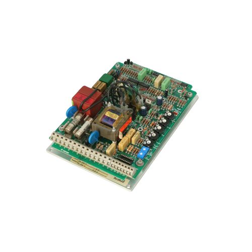
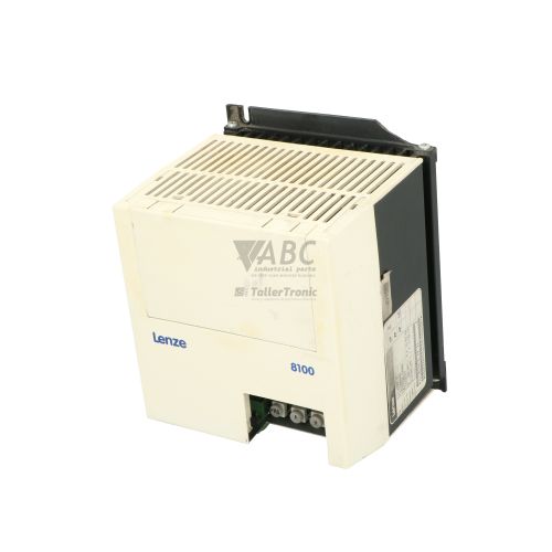
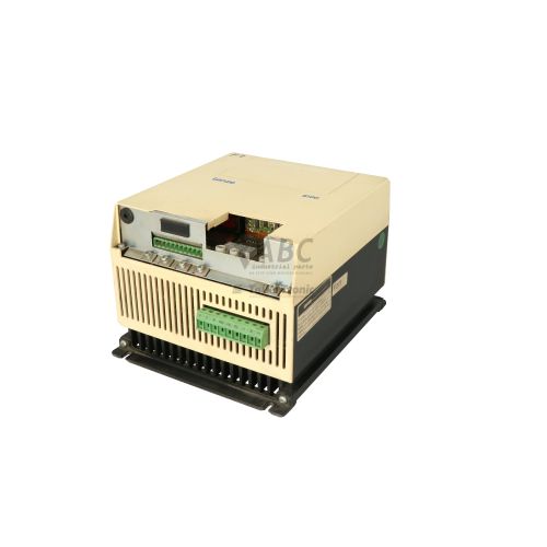
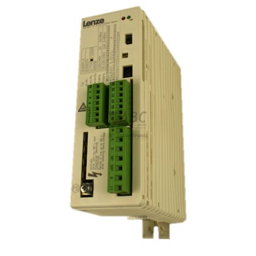
Product photos are for illustration purposes only and may differ from the actual product delivered.
Some of the content on this page was created with the help of AI. While we strive to provide accurate and up-to-date information, errors may occur.