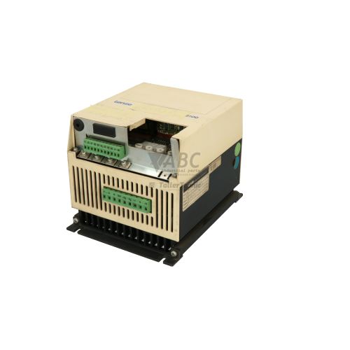
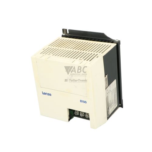
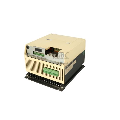
Lenze 8104_E.4H.12 Frequency Inverter | 8100 Series 3kW



Het item werd toegevoegd aan uw offerteaanvraag
Product Information
The Lenze 8104_E.4H.12 is a 3.0 kW frequency inverter from the 8100 Series designed for variable speed control of standard three-phase AC induction motors in industrial applications such as conveyors, pumps, and ventilation fans. Operating from a 3-phase supply of 400 V to 480 V AC with an operational range of 320 V to 528 V AC, this compact drive delivers a continuous rated output current of 7.0 A and maximum output frequencies up to 480 Hz. Built in an IP20 enclosure for vertical panel mounting inside control cabinets, the inverter utilizes linear or quadratic V/f characteristic control and incorporates an integrated brake chopper for dynamic stopping of high-inertia loads.
Connecting the drive into automated control systems is accomplished via programmable digital and analog screw terminals, alongside a front option slot that accommodates pluggable modules such as serial LECOM-A/B (RS-232/RS-485) adapters or PROFIBUS-DP fieldbus interfaces. Putting a replacement unit into service requires transferring configuration parameters, which can be completed either through direct keypad copying between drives with matching firmware or using Lenze Global Drive Control (GDC) software. All parameter sets reside in non-volatile EEPROM storage to prevent data loss during power outages, and ABC Industrial Parts can support maintenance technicians with spare unit procurement and parameter backup restoration.
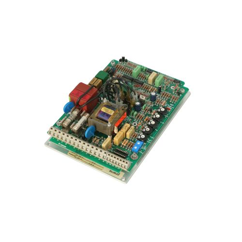
Diagnostic monitoring is facilitated by a bi-color Red/Green Status LED indicating operating state, warnings, and TRIP conditions, alongside display readouts and software diagnostic windows within Global Drive Control. The integrated TRIP memory buffer tracks recent faults accessible via codes C0138 and C0003, detailing errors such as overcurrent (OC1, OC2, OC5), DC bus overvoltage or undervoltage (OU, LU), heatsink or motor thermal overload (OH, OH4, OLE), earth faults (IPE), and communication timeouts (CE0). When non-volatile memory errors like EEPROM failure (EE) or internal output stage faults occur, internal hardware components are not field-serviceable, making drive replacement or hardware repair through ABC Industrial Parts the most reliable solution to restore equipment operation.
Technical Specifications
| Manufacturer | Lenze |
| Part Number | 8104_E.4H.12 |
| Model / Type | 8104 E.4H.12 |
| Product Family | 8100 Series |
| Component Type | Frequency Inverter |
| Rated Power | 3.0 kW |
| Supply Voltage Range | 3x 400 / 480 V AC (320 – 528 V AC) |
| Rated Output Current | 7.0 A |
| Maximum Output Frequency | 480 Hz |
| Control Method | V/f characteristic control (linear or quadratic) |
| Brake Transistor | Integrated Brake Chopper |
| Protection Rating | IP20 |
| Mounting Type | Control Cabinet / Panel Mount |
Programming and Configuration
Drive parameterization for the Lenze 8104_E.4H.12 frequency inverter is performed using the pluggable Lenze keypad operating module or through Lenze Global Drive Control (GDC) PC software. System parameters, motor characteristics, and ramp profiles are written to internal non-volatile EEPROM memory, securing configuration data against power shutdowns.
When commissioning a spare drive, parameter transfer can be executed rapidly by uploading the saved parameter set using GDC software or by transferring parameter data directly using the pluggable keypad module between units. Loading factory default settings can also be executed to clear corrupted parameter tables prior to re-commissioning.
Communication and System Integration
The 8104_E.4H.12 inverter integrates into industrial control architectures via standard screw control terminals. Digital inputs process start, stop, and direction commands, while analog inputs receive variable speed reference signals.
Fieldbus and higher-level network communications are added via the drive's front option slot. Compatible option modules include LECOM-A/B serial adapters for RS-232 and RS-485 interfaces, as well as PROFIBUS-DP fieldbus interface modules for real-time control and remote diagnostic access from host PLCs.
Diagnostics and Status Indication
Operational monitoring on the 8104_E.4H.12 is indicated by the front panel Red/Green Status LED, which signals standard operation, active warnings, and TRIP conditions via solid or flashing states. Operational data can also be viewed through the optional pluggable keypad display or the Global Drive Control diagnostic panel.
Historical fault analysis is retrieved using TRIP memory buffer codes C0138 and C0003. This buffer records recent system trips, including supply undervoltage, output overcurrent, temperature threshold exceeded, and communication interface timeouts.
Status LED Indicators
| LED | Color/Status | Meaning |
|---|---|---|
| Status LED | Red/Green - Solid / Flashing | Indicates operational status, TRIP fault, or warning condition |
Replacement and Spare Part Considerations
When installing a replacement Lenze 8104_E.4H.12 inverter, verify that the complete part number matches the original unit. Because motor mapping, maximum frequency limits, and control terminal functions depend on parameters stored in EEPROM memory, a spare drive must be loaded with the machine's specific configuration prior to operation.
Parameter transfer can be accomplished by copying the memory structure directly using a pluggable keypad module or downloading a backup parameter file via Lenze Global Drive Control (GDC) software. If the original inverter has suffered internal hardware damage or an EEPROM corruption error, parameters should be restored from documented backup files to re-establish full functionality.
Error Codes & Fault Codes
The following error codes may be displayed during operation or diagnostics:
| Code | Name | Description | Possible Cause | Recommended Action |
|---|---|---|---|---|
| OC1 | Short Circuit / Overcurrent Acceleration | Output current limit exceeded during motor acceleration phase. | Acceleration time too short, motor cable short circuit, ground fault, or damaged power stage. | Check motor cable and winding insulation; increase acceleration time; check drive sizing. |
| OC2 | Short Circuit / Overcurrent Deceleration | Output current limit exceeded during motor deceleration phase. | Deceleration time set too short; mechanical jam or high load inertia. | Increase deceleration time or install braking resistor. |
| OC5 | Short Circuit / Overcurrent Constant Speed | Short circuit or overcurrent detected during steady-state constant speed operation. | Sudden load impulse, motor cable failure, or internal inverter output stage failure. | Check motor and wiring for short circuits; check for mechanical blockages. Internal failure requires hardware replacement. |
| OU | DC Bus Overvoltage | DC bus voltage exceeded upper threshold level. | Excessive regenerative energy fed back from motor during deceleration; deceleration time too short. | Increase deceleration time or connect external braking resistor. |
| LU | DC Bus Undervoltage | DC link bus voltage fell below lower operational threshold. | Mains supply voltage drop, phase loss, or weak supply network. | Check mains voltage, supply fuses, and line connections. |
| OH | Heatsink Overtemperature | Heatsink temperature exceeded internal maximum limit (>85 °C). | Insufficient cooling airflow, dirty heatsink, fan failure, or high ambient temperature. | Clean heatsink fins, verify cabinet ventilation, check cabinet fan operation. |
| OH4 | Motor Overtemperature | Motor temperature switch or thermistor open circuit / triggered. | Motor thermal overload, thermistor cable disconnected or damaged. | Allow motor to cool down; check motor thermal protection switch and wiring. |
| OLE | Motor Overload Ixt | Calculated motor overload Ixt function limit reached. | Continuous motor operation under excessive mechanical load. | Check drive load, mechanical binding, or motor current settings. |
| IPE | Earth Fault / Ground Fault | Earth fault detected on motor phases. | Ground leak in motor insulation, damaged motor cable, or internal sensor failure. | Check motor insulation resistance with megohmmeter and inspect cabling. |
| EE | EEPROM Fault | Internal memory fault or corrupted EEPROM data. | Corrupted non-volatile parameter memory or internal micro-controller board failure. | Load factory default parameters. Internal hardware failure — return unit for repair or replace unit if fault persists. |
| CE0 | Communication Error | Time-out or error on communication module / LECOM interface. | Loose communication cable, host controller timed out, or faulty communication module. | Check fieldbus cabling, baud rate, and bus termination switches. |
| LP | Mains Phase Loss | One phase of incoming AC mains supply missing or severely unbalanced. | Blown input line fuse, loose power wiring connection, or line drop. | Check line supply fuses, mains supply voltage stability, and line connections. |
Frequently Asked Questions
How do I transfer parameters from a failed Lenze 8104_E.4H.12 to a spare unit?
Parameters can be copied directly using the pluggable Lenze operating keypad module between units with matching firmware, or by connecting a PC running Lenze Global Drive Control (GDC) software to upload the parameter file and download it into the replacement drive.
What causes an OC1 or OC5 fault code on the 8104_E.4H.12 inverter?
An OC1 fault indicates output overcurrent during acceleration, typically caused by overly aggressive acceleration ramps, motor cable short circuits, or ground faults. An OC5 fault indicates overcurrent at constant speed, caused by mechanical load spikes, short circuits, or damaged power electronics.
Does the 8104_E.4H.12 drive support external braking resistors?
Yes, the 8104_E.4H.12 features a built-in 4H execution brake chopper (transistor), allowing an external braking resistor to be wired directly to the power terminals for dynamic braking.
Which communication interfaces are supported by this inverter?
The drive features a front option slot that supports LECOM-A/B modules for RS-232 and RS-485 serial communication, as well as PROFIBUS-DP fieldbus interface modules.
What action should be taken if an EE fault code is displayed?
An EE code points to corrupted EEPROM parameter memory. Attempt to reload factory default parameters. If the fault persists after re-parameterization, internal microcontroller hardware failure is indicated, requiring drive replacement or repair.
Take advantage of our exchange formula
A defective product does not have to be worthless. At ABC Industrial Parts, you can hand in defective products and immediately benefit from a discount on your new purchase. This is a smart way to save money while contributing to a circular economy.
Play it safe with our warranty conditions
Industrial plants prefer to keep running invariably, no matter what. Therefore, it is essential that you can rely on high-quality products and/or sustainable repairs. With our warranty conditions, you can count on certainty, whether you choose new, used or repaired products.
Data backup and recovery
Have you lost valuable parameters or data due to a malfunction while the manufacturer no longer provides support? At ABC Industrial Parts, we help you secure this data, both for common and specific products.
Specific firmware and hardware versions
If you are working with specific hardware or firmware versions that are no longer available from the manufacturer, ABC Industrial Parts is your partner. When making your enquiry, clearly state which versions you need, we will then look at the possibilities of supplying those versions, so that your installations continue to function optimally.
Disclaimer:
We are not an authorised distributor of Lenze.
Product photos are for illustration purposes only and may differ from the actual product delivered.
Some of the content on this page was created with the help of AI. While we strive to provide accurate and up-to-date information, errors may occur.