Lenze 8106_E.4I.12 347426 Frequency Inverter Drive



Het item werd toegevoegd aan uw offerteaanvraag
Product Information
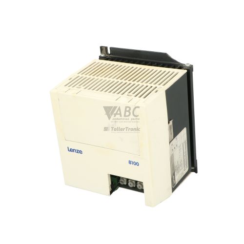
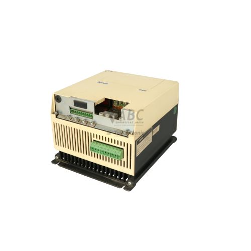
The Lenze 8106_E.4I.12, also designated under model number 347426, is a 4.0 kW frequency inverter from the Lenze 8100 product family. Designed to regulate the speed of standard 3-phase AC induction motors, this drive operates on a 3-phase supply voltage range from 320 V AC to 528 V AC. It provides a continuous rated output current of 8.8 A at 400 V AC and supports a 150% overload capability of 13.2 A for up to 60 seconds during acceleration or high torque demand. Utilizing linear and quadratic V/f characteristic control across an output frequency range of 0 to 480 Hz, the inverter allows programmable switching frequencies of 2, 4, 8, and 16 kHz to optimize acoustic performance and minimize motor noise.
Connecting the drive into an automated process relies on built-in digital inputs, multi-range analog setpoint inputs supporting 0–10 V, 0–20 mA, and 4–20 mA signals, and a fault signaling changeover relay output across terminals 21, 22, and 24. System integration can be expanded using plug-in fieldbus options such as the LECOM 2102IB module for RS232/RS485 communication or the CANopen 2171IB module. Putting a replacement inverter into service is rarely plug-and-run, as internal parameters must be configured to match motor dynamics and control logic. Parameter settings can be cloned and restored from the drive's internal non-volatile EEPROM memory using the Lenze 33.810 plug-in keypad panel or Global Drive Control (GDC) PC software. Technicians at ABC Industrial Parts can assist with parameter extraction and data transfer to ensure a replacement unit is configured accurately before installation.
Operational status and active drive states are indicated via a front-panel Red/Green Status LED that displays solid or flashing light patterns. Detailed real-time diagnostics and error codes are accessed directly through keypad display parameter P000 or remotely over a LECOM connection using GDC software. In the event of a TRIP condition, the internal relay toggles status terminals 21, 22, and 24 to inform external control systems. Diagnostic trip codes include LU for supply undervoltage, OU for overvoltage during braking, and OH for heatsink overtemperature. While faults like phase loss (LP) or overcurrent (OC1, OC2, OC5) point to external supply or motor cabling issues, hardware errors such as H0 indicate internal control board failures that are not field-serviceable. When internal faults persist, acquiring a fully tested replacement unit from ABC Industrial Parts provides a direct route to restoring production.
Technical Specifications
| Manufacturer | Lenze |
| Part Number | 8106_E.4I.12 |
| Model / Type | 347426 |
| Product Family | Lenze 8100 |
| Component Type | Frequency Inverter |
| Rated Power | 4.0 kW |
| Supply Voltage Range | 320 - 528 V AC |
| Rated Output Current | 8.8 A |
| Maximum Output Current | 13.2 A (150% overload for 60s) |
| Output Frequency Range | 0 - 480 Hz |
| Switching Frequency | 2, 4, 8, 16 kHz |
| Control Method | V/f Characteristic Control |
| Analog Input Signal Ranges | 0-10 V, 0-20 mA, 4-20 mA |
| Relay Output Terminals | Fault changeover relay (Terminals 21, 22, 24) |
Programming and Configuration
Configuring the Lenze 8106_E.4I.12 inverter is carried out using either the plug-in Lenze 33.810 keypad panel or the Global Drive Control (GDC) PC software. The drive relies on non-volatile internal EEPROM memory to store system parameters, user setpoints, acceleration/deceleration ramps, and V/f curves, ensuring operational settings remain intact during power outages.
During drive commissioning or replacement, parameter sets can be read out and cloned directly using the 33.810 keypad or transferred via a PC connected through a LECOM module running GDC software. Real-time operational values and error logs can be reviewed via parameter P000. In situations where parameter corruption occurs or a fresh configuration is required, a factory parameter reset can be executed to load default factory settings before re-entering motor data.
Communication and System Integration
The Lenze 8106_E.4I.12 frequency inverter features terminal control connections alongside optional fieldbus interface modules for system integration. Standard control interfaces include digital inputs for run commands and multi-range analog inputs that accept 0–10 V, 0–20 mA, or 4–20 mA setpoint signals. A dedicated changeover relay output on terminals 21, 22, and 24 provides fault signaling to higher-level controllers.
For networked control architectures, the inverter supports optional plug-in modules. The LECOM 2102IB fieldbus module enables point-to-point or multi-drop serial communication over RS232 or RS485 interfaces. Alternatively, the CANopen 2171IB module allows integration into CANopen fieldbus networks for high-speed parameter access and remote drive control.
Diagnostics and Status Indication
The drive incorporates visual and digital diagnostic tools to monitor operational state and troubleshoot faults. A multi-color Red/Green Status LED located on the front panel provides instant visual feedback, displaying solid or flashing illumination depending on whether the drive is running normally, warning of an impending limit, or tripped on a fault.
Detailed diagnostic messages and active error codes are retrievable through parameter P000 via the optional 33.810 keypad display. Additionally, when connected via a LECOM interface module, Global Drive Control (GDC) software provides comprehensive live diagnostics and historical error tracking directly on a PC.
Status LED Indicators
| LED | Color/Status | Meaning |
|---|---|---|
| Status | Red/Green - Solid/Flashing | Front panel indicator displaying drive operational status and fault conditions |
Replacement and Spare Part Considerations
When replacing a Lenze 8106_E.4I.12 frequency inverter (part number 347426), verify that the replacement drive matches the power rating of 4.0 kW and output current rating of 8.8 A. Confirm that input AC supply levels are within 320 V AC to 528 V AC to prevent undervoltage (LU) or overvoltage (OU) trips.
A replacement unit cannot operate effectively without transferring the original drive's application parameters. Before removing the existing unit, back up parameter sets to the 33.810 keypad panel or upload them to Global Drive Control (GDC) software via a LECOM module. Once the replacement inverter is wired, load the stored parameters to align motor data, I/O functions, and switching frequency settings.
Error Codes & Fault Codes
The following error codes may be displayed during operation or diagnostics:
| Code | Name | Description | Possible Cause | Recommended Action |
|---|---|---|---|---|
| LU | Undervoltage | DC bus voltage dropped below lower limit threshold. | Mains voltage too low, supply phase loss, or power supply interruption. | Check mains voltage supply lines and fuses. |
| OU | Overvoltage | DC bus voltage exceeded maximum threshold limit. | Deceleration time too short, regenerative energy returned from motor too high. | Increase deceleration ramp time or connect/check braking resistor/brake chopper module. |
| OH | Heatsink Overtemperature | Heatsink temperature exceeded permissible limit. | Insufficient cooling airflow, ambient temperature too high, cooling fan failure, or heatsink dirty. | Clean heatsink fins, check cabinet ventilation, ensure operating temperature is within specification. |
| OH4 | Motor Overheat Warning / Fault | Motor temperature sensor (PTC/TK) detected overtemperature. | Motor thermal overload, blocked cooling, or disconnected sensor. | Check motor thermal load, check fan on motor, verify PTC/TK wire connections. |
| OC1 | Short Circuit / Overcurrent Acceleration | Instantaneous output current threshold exceeded during acceleration. | Short circuit or earth fault on motor cables, acceleration time set too short, motor incorrectly dimensioned. | Check motor winding resistance and cable insulation. Increase acceleration time. |
| OC2 | Overcurrent Deceleration | Output current limit exceeded during deceleration ramp. | Deceleration time too short or regenerative braking overload. | Increase deceleration ramp time. |
| OC5 | I x t Overload Drive | Continuous overload threshold (I x t limit) of the drive exceeded. | Drive continuously operated above rated current load. | Reduce mechanical load on motor or select larger capacity inverter. |
| EE | EEPROM Fault | Internal memory checksum error during parameter read/write. | Internal memory corruption or hardware memory module failure. | Perform factory parameter reset (load default settings). Internal hardware fault — return unit for repair if fault persists. |
| CE | Communication Error | Communication breakdown via LECOM / fieldbus module. | Cable disconnection, incorrect baud rate, noise interference, or plug-in module loose. | Check communication cable, module seating, and baud rate parameters. |
| LP | Phase Fault | Loss of a mains supply phase. | Unbalanced supply voltage or blown input fuse. | Check supply line voltages and fuses on input AC terminals. |
| H0 | Hardware Fault | Internal control board or power unit error detected during self-test. | Defective internal hardware component. | Internal hardware fault — return unit for repair or replace inverter. |
Frequently Asked Questions
How do I back up and restore parameters on the Lenze 8106_E.4I.12 drive?
Parameter sets are stored in non-volatile internal EEPROM memory and can be cloned using the Lenze 33.810 plug-in keypad panel or uploaded and downloaded using Lenze Global Drive Control (GDC) PC software connected through a LECOM module.
What communication fieldbus modules are supported by the Lenze 8106_E.4I.12?
The drive supports plug-in fieldbus modules including the LECOM 2102IB for RS232 or RS485 serial communication and the CANopen 2171IB module for CANopen network integration.
What does fault code H0 indicate on this frequency inverter?
Fault code H0 indicates an internal hardware fault on the control board or power unit detected during a self-test. This error is not field-serviceable and requires returning the unit for repair or replacing the inverter.
What analog setpoint signals can be connected to the drive?
The inverter features multi-range analog setpoint inputs accepting 0–10 V voltage signals as well as 0–20 mA and 4–20 mA current signals.
What are the output current and overload capabilities of the 8106_E.4I.12?
The drive delivers a continuous rated output current of 8.8 A at 400 V AC and can handle a peak overload current of 13.2 A (150%) for up to 60 seconds.
Take advantage of our exchange formula
A defective product does not have to be worthless. At ABC Industrial Parts, you can hand in defective products and immediately benefit from a discount on your new purchase. This is a smart way to save money while contributing to a circular economy.
Play it safe with our warranty conditions
Industrial plants prefer to keep running invariably, no matter what. Therefore, it is essential that you can rely on high-quality products and/or sustainable repairs. With our warranty conditions, you can count on certainty, whether you choose new, used or repaired products.
Data backup and recovery
Have you lost valuable parameters or data due to a malfunction while the manufacturer no longer provides support? At ABC Industrial Parts, we help you secure this data, both for common and specific products.
Specific firmware and hardware versions
If you are working with specific hardware or firmware versions that are no longer available from the manufacturer, ABC Industrial Parts is your partner. When making your enquiry, clearly state which versions you need, we will then look at the possibilities of supplying those versions, so that your installations continue to function optimally.
Disclaimer:
We are not an authorised distributor of Lenze.
Product photos are for illustration purposes only and may differ from the actual product delivered.
Some of the content on this page was created with the help of AI. While we strive to provide accurate and up-to-date information, errors may occur.