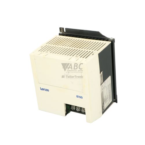
Lenze E82EV402_4B 8200 Vector 4.0 kW Frequency Inverter



Het item werd toegevoegd aan uw offerteaanvraag
Product Information
The Lenze E82EV402_4B is an IP20-rated frequency inverter from the 8200 Vector product family, engineered to deliver controlled motor speed and torque regulation for three-phase AC motors in industrial drives. Built with a modular structure that separates the power unit from control and function modules, this base unit operates on a 3-phase AC supply voltage range of 320 to 550 V AC (400/500 V AC nominal). It provides a rated output power of 4.0 kW and a continuous output current of 9.5 A, with a peak maximum output current of 14.3 A supporting a 150% overload capacity for up to 60 seconds. The drive delivers an output frequency range of 0 to 480 Hz with a factory-set 8 kHz switching frequency, making it suitable for applications such as conveyor belt speed control, industrial pumps, ventilation fan flow regulation, and packaging machinery drive axes.
Integrating a replacement unit into an active control system requires aligning fieldbus options and parameter sets. The E82EV402_4B features a front-facing plug-in slot designed to accommodate optional operator units such as the Keypad XT (E82ZBC), PC communication adapters using Lenze Global Drive Control (GDC) software, or function modules including the E82ZAFSC, E82ZAFCC, and E82ZAFPC for PROFIBUS and CANopen integration. Replacing a unit is streamlined because the inverter incorporates internal non-volatile EEPROM memory capable of storing up to four complete parameter sets. Original parameter settings can be extracted from a donor unit or loaded from a saved configuration file via GDC software or the Keypad XT before putting the spare into service. ABC Industrial Parts can assist in sourcing and preparing replacement units to minimize process downtime during drive substitution.
Diagnostics and status monitoring on the E82EV402_4B are handled via front panel LEDs and internal system parameters. A green Ready LED indicates power status and controller operation, while a red Fault/Trip LED indicates active trip faults or current/voltage warnings. Technicians can perform deeper troubleshooting by accessing the active fault code parameter C0013 or reviewing the fault history buffer in parameter C0168 using the Keypad XT or GDC software. Common field trip codes include overcurrent conditions (OC1, OC2, OC5), DC bus voltage issues (OU, LU), and system thermal limits (OH, OH4, OH7). When internal memory errors like EE0 or EEr, or hardware supply failures such as H05 occur, the internal board components are not field-serviceable, making drive replacement or testing by ABC Industrial Parts the standard route back to operation.
Technical Specifications
| Manufacturer | Lenze |
| Part Number | E82EV402_4B |
| Model / Type | 8200 Vector E82EV402_4B |
| Component Type | Frequency Inverter |
| Product Family | 8200 Vector |
| Rated Power | 4.0 kW |
| Supply Voltage Range | 320 - 550 V AC |
| Rated Output Current | 9.5 A |
| Maximum Output Current | 14.3 A |
| Power Dissipation | 160 W |
| Output Frequency Range | 0 - 480 Hz |
| Switching Frequency | 8 kHz |
| Protection Rating | IP20 |
Programming and Configuration
Parameterization of the Lenze E82EV402_4B frequency inverter is managed using either the plug-in Keypad XT (E82ZBC) or Lenze Global Drive Control (GDC) software connected through a front-panel interface adapter. The inverter houses non-volatile EEPROM memory engineered to store up to four complete parameter sets, allowing multi-application setups or parameter set switching during operational changes.
During drive commissioning or parameter cloning, configuration files can be uploaded from the drive to GDC software or transferred directly through the Keypad XT module. Important runtime parameters, such as active fault indications in C0013 and historical trip logs in C0168, provide direct insight into drive setup and operational history. V/f characteristic curves (linear and quadratic), sensorless vector control parameters, and maximum frequency limits are configured within these parameter structures to match motor specifications.
Communication and System Integration
The modular design of the Lenze 8200 Vector series separates core power electronics from communication and I/O function modules. The E82EV402_4B supports plug-in function modules such as the E82ZAFSC, E82ZAFCC, and E82ZAFPC, allowing flexible interface adaptation to higher-level automation networks without altering the power hardware.
Through these option modules, the inverter integrates into fieldbus systems including PROFIBUS and CANopen, enabling process data exchange, speed references, and control commands from a master PLC. System bus communication errors (CE0) can be prevented during commissioning by verifying fieldbus cabling, shield grounding, terminal resistors, station addresses, and baud rate settings.
Diagnostics and Status Indication
The E82EV402_4B provides front panel visual indication alongside parameter-based diagnostic monitoring. Two LEDs on the front panel display the immediate operational state: the green Ready LED signals power and controller status, while the red Fault/Trip LED signals warnings or active drive shutdowns.
Detailed diagnostic analysis is conducted by reading parameter C0013 for the active fault code or parameter C0168 to inspect the saved fault history log. These diagnostic features assist maintenance personnel in distinguishing between external field trip conditions, mains power interruptions, and internal hardware failures.
Status LED Indicators
| LED | Color/Status | Meaning |
|---|---|---|
| Ready (Green) | Green - Solid / Blinking / Off | Off: Drive unpowered or internal failure. On: Inverter ready/running. Blinking: Controller inhibited or enabled. |
| Fault / Trip (Red) | Red - Solid / Blinking / Off | Off: Normal operation. On: Active TRIP fault present. Blinking: Warning / current or voltage limit reached. |
Replacement and Spare Part Considerations
The Lenze 8200 Vector series has been discontinued by the manufacturer, making direct physical and electrical replacement with an identical E82EV402_4B unit essential for maintaining existing production equipment without redesigning the control cabinet. Because the modular system separates power electronics from interface options, original plug-in function modules (such as E82ZAFSC, E82ZAFCC, or E82ZAFPC) can be attached directly onto the replacement power unit.
Before placing a replacement E82EV402_4B inverter into active operation, parameter settings must be transferred to the replacement unit's internal EEPROM memory. Up to four parameter sets can be written using Lenze Global Drive Control (GDC) software or the Keypad XT module. Verifying parameter consistency ensures matching V/f characteristic curves, overload thresholds, and fieldbus node addressing.
Error Codes & Fault Codes
The following error codes may be displayed during operation or diagnostics:
| Code | Name | Description | Possible Cause | Recommended Action |
|---|---|---|---|---|
| OC1 | Short Circuit / Earth Fault | Overcurrent during acceleration or short circuit/earth fault at output | Short circuit in motor cable or motor winding; earth fault; acceleration ramp too short; motor cable too long | Check motor and output wiring for short circuits and ground faults; increase acceleration time; check motor sizing |
| OC2 | Overcurrent during Deceleration | Output current exceeds trip limit during deceleration | Deceleration ramp too short; braking energy too high without braking resistor | Increase deceleration ramp time; fit optional braking module / braking resistor |
| OC5 | Overcurrent at Constant Speed | Output current exceeds trip threshold during steady-state operation | Abrupt load change; mechanical blockage or overload; motor improperly sized | Check mechanical load for jam or binding; check motor parameter settings |
| OU | DC Bus Overvoltage | Intermediate circuit DC voltage exceeds threshold (approx. 770 V DC for 400V drives) | Excessive regenerative energy from motor during deceleration; deceleration time too fast; missing braking resistor | Extend deceleration time; connect braking module and resistor; check mains supply voltage |
| LU | DC Bus Undervoltage | Intermediate circuit DC voltage fell below lower threshold | Mains supply voltage too low; phase failure on mains supply; transient power interruption | Check supply line voltage and phase connections; verify input fuses |
| OH | Heatsink Overtemperature | Heatsink temperature exceeded permissible limit (> 90°C) | Inadequate cooling; ambient temperature too high (> 45°C/50°C); fan failure or clogged heat sink fins; continuous overload | Clean heatsink cooling fins; verify fan operation; improve cabinet ventilation |
| OH4 | Motor Overtemperature | Motor thermal sensor / PTC contact triggered on PTC terminals | Motor thermal overload; cooling fan on motor defective; PTC sensor wire broken | Allow motor to cool down; check mechanical load on motor; check motor PTC connection |
| OH7 | Internal Ambient Overtemperature | Internal control board temperature too high | Enclosure internal temperature exceeded limit | Improve enclosure cooling and airflow around drive |
| NMAX | Overspeed | Motor speed higher than set maximum frequency limit | Incorrect speed feedback scaling or overshoot during fast acceleration | Check speed controller settings and maximum frequency limit parameter |
| EE0 | Memory Fault EEPROM | Internal EEPROM memory read/write error during operation | Internal hardware failure or memory corruption caused by strong EMC interference | Internal hardware fault — reset parameter to default values; if fault persists, unit requires return for repair or replacement |
| EEr | EEPROM Read Error | Internal non-volatile parameter memory cannot be read | Internal EEPROM hardware failure | Internal hardware fault — contact service or replace unit |
| H05 | Internal Hardware Error | Internal control unit power supply or board hardware fault detected | Control board component failure | Internal hardware fault — field-repair not possible; return unit for factory repair or replacement |
| CE0 | System Bus / Communication Error | Interruption or timeout on process data / system bus communication | Fieldbus cable disconnected; master PLC stopped; incorrect baud rate or station address | Check fieldbus wiring, shield grounding, termination resistors, and master controller status |
| LP1 | Motor Phase Failure | One motor phase missing or open circuit at inverter output | Motor cable broken; contactor open on output side; motor winding disconnected | Check output motor wiring and terminal tightness; verify motor winding resistances |
| P12 | Mains Phase Failure | Failure of one supply mains phase detected | Blown supply fuse; unbalanced mains supply | Check incoming 3-phase mains voltage and line fuses |
Frequently Asked Questions
How do I transfer parameters to a replacement Lenze E82EV402_4B drive?
Parameter sets stored in the internal non-volatile EEPROM can be transferred using the Keypad XT (E82ZBC) operator module or Lenze Global Drive Control (GDC) software via a PC interface adapter. The inverter can retain up to four complete parameter sets.
What plug-in modules are compatible with the Lenze E82EV402_4B inverter?
The E82EV402_4B supports Lenze 8200 Vector function modules such as the E82ZAFSC, E82ZAFCC, and E82ZAFPC, as well as the Keypad XT (E82ZBC) module for local diagnostics and parameter setup.
What does an OC1 fault code indicate on the E82EV402_4B?
An OC1 fault code indicates an overcurrent condition during acceleration or a short circuit/earth fault at the inverter output terminals. Recommended steps include inspecting motor cabling and motor windings for short circuits or ground faults, and verifying acceleration ramp times.
How can I check active faults and fault history on the E82EV402_4B?
Active fault codes can be read directly from parameter C0013, while historical trip logs are stored in buffer C0168. Both parameters are accessible using the Keypad XT module or GDC software.
Can internal EEPROM errors like EE0 or EEr be repaired in the field?
EE0 and EEr indicate internal memory corruption or hardware failure. While resetting parameters to factory defaults may resolve temporary memory corruption, persistent hardware fault codes (such as EE0, EEr, or H05) require drive replacement or testing by a repair service.
Take advantage of our exchange formula
A defective product does not have to be worthless. At ABC Industrial Parts, you can hand in defective products and immediately benefit from a discount on your new purchase. This is a smart way to save money while contributing to a circular economy.
Play it safe with our warranty conditions
Industrial plants prefer to keep running invariably, no matter what. Therefore, it is essential that you can rely on high-quality products and/or sustainable repairs. With our warranty conditions, you can count on certainty, whether you choose new, used or repaired products.
Data backup and recovery
Have you lost valuable parameters or data due to a malfunction while the manufacturer no longer provides support? At ABC Industrial Parts, we help you secure this data, both for common and specific products.
Specific firmware and hardware versions
If you are working with specific hardware or firmware versions that are no longer available from the manufacturer, ABC Industrial Parts is your partner. When making your enquiry, clearly state which versions you need, we will then look at the possibilities of supplying those versions, so that your installations continue to function optimally.
Disclaimer:
We are not an authorised distributor of Lenze.
Product photos are for illustration purposes only and may differ from the actual product delivered.
Some of the content on this page was created with the help of AI. While we strive to provide accurate and up-to-date information, errors may occur.