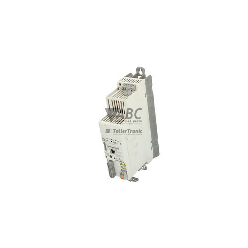
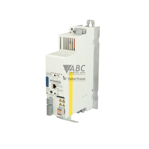
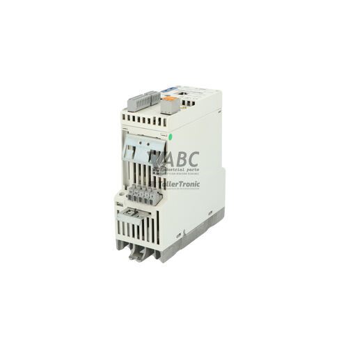
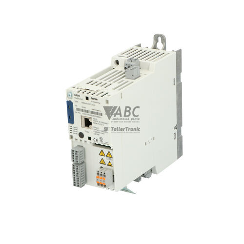
Lenze E84AVSCE1524SB0 8400 StateLine C 1.5 kW Frequency Inverter



Het item werd toegevoegd aan uw offerteaanvraag
Product Information
The Lenze E84AVSCE1524SB0 is a panel-mounted frequency inverter from the 8400 StateLine C series within the Lenze 8400 Inverter Series. Engineered for precise motor speed and torque regulation, this 1.5 kW drive operates on a 3-phase AC supply voltage ranging from 320 V to 528 V at 45 to 65 Hz. Delivering a rated output current of 3.9 A at 400 V and 3.3 A at 480 V, the unit provides motor control across an output frequency range of 0 to 599 Hz using linear or square-law V/f characteristics, VFCplus control, and Sensorless Vector Control. Housed in an IP20 enclosure for control cabinet installation, it incorporates an integrated braking chopper for dynamic deceleration and built-in Safe Torque Off (STO) certified to SIL 3 and PL e.
For system connectivity, the inverter includes an integrated CANopen bus operating up to 1 Mbit/s, alongside dedicated I/O terminals comprising five digital inputs, one digital output, one relay output, one analog input, and one analog output. Optional fieldbus communication modules can be added for networks such as PROFINET, PROFIBUS-DP, EtherNet/IP, EtherCAT, and Modbus RTU. Commissioning a replacement unit does not require extensive PC programming when transferring settings via the pluggable Lenze E84AYM200 memory module, which holds the parameter set for rapid insertion into a donor drive. When replacing an existing unit, matching the parameter configuration, safety wiring across the STO inputs, and fieldbus node parameters ensures full compatibility, with ABC Industrial Parts offering technical support for spare unit preparation and configuration transfers.
Diagnostic status is communicated directly on the front panel via dedicated LEDs, including DRIVE READY for operational status, DRIVE ERROR for fault warnings, and a CANopen/Bus indicator for network state. The drive also maintains an internal error memory logging the last eight fault events, accessible via the X400 keypad or EASY Navigator software using a USB diagnostic adapter. Common operational faults include overcurrent conditions (OC1, OC2, OC5), overvoltage (OU), undervoltage (LU), and thermal overload warnings (OH, OH4). If parameter initialization errors (PI) occur or hardware components sustain internal damage, field servicing may be unfeasible, making a fully tested replacement drive from ABC Industrial Parts the most effective route to minimize operational downtime.
Technical Specifications
| Manufacturer | Lenze |
| Part Number | E84AVSCE1524SB0 |
| Model / Type | 8400 StateLine C |
| Product Family | 8400 Inverter Series |
| Component Type | Frequency Inverter |
| Rated Power | 1.5 kW |
| Supply Voltage Range | 320 - 528 V AC |
| Supply Frequency Range | 45 - 65 Hz |
| Rated Output Current (400V) | 3.9 A |
| Rated Output Current (480V) | 3.3 A |
| Output Frequency Range | 0 - 599 Hz |
| Switching Frequency | 8 kHz |
| Control Modes | V/f, VFCplus, Sensorless Vector Control (SLVC) |
| Safety Function | Safe Torque Off (STO) SIL 3 / PL e |
| Brake Chopper | Integrated |
| Integrated System Bus | CANopen |
| Digital Inputs / Outputs | 5 Inputs / 1 Output |
| Relay Outputs | 1 |
| Analog Inputs / Outputs | 1 Input / 1 Output |
| Mounting Type | Panel Mounting |
| IP Rating | IP20 |
Programming and Configuration
Configuring the Lenze 8400 StateLine C inverter is performed through the EASY Navigator software suite or locally using the X400 Keypad (E84AVTKE). Connected via the Lenze USB Diagnostic Adapter (E84AVDCEU), engineering software enables parameter extraction, online diagnostics, and fine-tuning of motor control loops. Key adjustable parameters include acceleration and deceleration ramps, speed limits, and control modes ranging from V/f characteristics to Sensorless Vector Control.
Parameter storage relies on the swappable Lenze E84AYM200 memory module. This physical EEPROM module stores the entire drive configuration, including network node addresses, control parameters, and fault parameters. By transferring the memory module directly from a decommissioned drive to a replacement unit, technicians can restore complete operational parameters without connecting a PC or reloading software project files.
Communication and System Integration
The E84AVSCE1524SB0 features a built-in CANopen system bus interface capable of communication speeds up to 1 Mbit/s. Integrated directly into the drive hardware, this interface supports standardized CANopen profiles for cyclic data exchange, control word commands, and status feedback within distributed motion control networks.
For installations using alternative fieldbus networks, the drive accommodates optional plug-in communication modules. Supported protocols include PROFINET (E84AYCER), PROFIBUS-DP (E84AYCPM), EtherNet/IP (E84AYCEO), EtherCAT (E84AYCET), and Modbus RTU. Integrating these modules enables direct fieldbus coupling to higher-level PLCs while maintaining local I/O handling across the drive's five digital inputs, single digital output, relay output, and analog I/O channels.
Diagnostics and Status Indication
The drive provides visual status indication via front-mounted LEDs. The DRIVE READY LED indicates operational readiness, while the DRIVE ERROR LED signals active faults or warning conditions. Network communication activity and errors on the CANopen bus are reflected by the dual-color CANopen / Bus LED displaying CAN-RUN and CAN-ERR states.
Comprehensive diagnostics are supported through an integrated error log memory that automatically stores the last eight fault events with parameter codes. Diagnostic values can be retrieved via the optional X400 keypad or through PC software using the USB diagnostic adapter, allowing precise identification of fault conditions such as overcurrent, thermal limits, or bus failures.
Status LED Indicators
| LED | Color/Status | Meaning |
|---|---|---|
| DRIVE READY | Green - Solid / Flashing | Operational readiness status of the inverter |
| DRIVE ERROR | Red - Solid / Flashing | Indicates drive fault or warning condition |
| CANopen / Bus LED | Green / Red - CAN-RUN / CAN-ERR | CANopen system bus communication status |
Replacement and Spare Part Considerations
When swapping an E84AVSCE1524SB0 frequency inverter, hardware ratings and parameter configurations must be matched. Because the 8400 StateLine C series is in its phase-out period, direct unit replacement with an identical E84AVSCE1524SB0 part number remains the most direct solution for existing control cabinets. Where system redesigns are planned, the Lenze i550 cabinet frequency inverter series serves as the recommended successor.
To carry out a hardware exchange, turn off power, disconnect main AC supply terminals (L1, L2, L3) and motor terminals (U, V, W), and remove control wiring from digital and analog I/O connectors. Remove the E84AYM200 memory module from the decommissioned inverter and insert it into the replacement drive prior to powering up. This transfers all parameters, fieldbus settings, and motor profiles without requiring software re-commissioning. Ensure STO inputs (S1/S2) are properly wired to 24 V DC safety circuits before resuming operation.
Error Codes & Fault Codes
The following error codes may be displayed during operation or diagnostics:
| Code | Name | Description | Possible Cause | Recommended Action |
|---|---|---|---|---|
| OC1 | Short circuit / Earth fault | Short circuit or ground fault detected on motor terminals (U, V, W). | Motor cable shorted, earth fault in motor winding, ramp time too short. | Check motor and motor cables for insulation and short circuits. Increase acceleration ramp time. |
| OC2 | Overcurrent during acceleration | Output current exceeded internal threshold during motor acceleration phase. | Acceleration time too short, motor overloaded or blocked, incorrect motor parameter setup. | Increase acceleration time (C00012), check motor sizing and load mechanism, verify motor control parameters. |
| OC5 | Overcurrent during deceleration | Output current exceeded threshold during motor deceleration. | Deceleration time too short, brake chopper/resistor not working or missing. | Increase deceleration time (C00013), check brake chopper or braking resistor connection. |
| OU | DC-bus overvoltage | DC bus voltage exceeded safe maximum limit (approx. 770 V DC). | Regenerative energy from high inertia load during deceleration without active brake chopper/resistor; mains supply transient. | Extend deceleration time, connect external brake resistor to terminals (+UG, RB), check mains supply voltage. |
| LU | DC-bus undervoltage | DC bus voltage dropped below minimum operation limit. | Mains supply voltage fail, phase loss, power supply drop under heavy load. | Check supply network voltage and fuses, verify AC power wiring on L1, L2, L3 terminals. |
| OH | Heatsink overtemperature | Power section heatsink temperature exceeded maximum threshold. | Inadequate control cabinet ventilation, fan failure, ambient temperature too high, continuous overload. | Clean heatsink fins, check cabinet cooling/fan, lower switching frequency or load. |
| OH4 | Motor thermal overload | Motor temperature sensor (PTC/KTY/PT1000) or internal motor thermal model triggered overtemperature fault. | Motor overloaded, insufficient motor cooling, defective thermal sensor. | Allow motor to cool down, check motor load and cooling fan, verify temperature sensor connections (T1, T2). |
| PI | Parameter initialization error | Data corruption detected during parameter load from memory module. | Memory module removed while writing, corrupt parameter set, incompatible hardware/firmware version. | Re-load factory default settings, re-download parameter file from EASY Navigator, or replace memory module. |
| NMAX | Maximum speed limit exceeded | Actual motor speed exceeded defined maximum speed limit. | Incorrect encoder feedback signal, overspeed driven by external mechanical load, improperly tuned speed loop. | Verify speed limit parameter (C00011), check motor load and encoder signals. |
| STO | Safe Torque Off active | Safety function Safe Torque Off safety input triggered. | Safety circuit open, STO input channels (S1/S2) turned off. | Check external safety circuit, E-stop button, safety relay contacts supplying 24V to STO inputs. |
Frequently Asked Questions
How do I copy parameters to a replacement Lenze E84AVSCE1524SB0 drive?
Parameter transfer can be accomplished without a PC by swapping the pluggable Lenze E84AYM200 memory module from the existing unit into the replacement inverter. Alternatively, parameters can be downloaded via EASY Navigator software using the Lenze USB Diagnostic Adapter (E84AVDCEU) or configured using the X400 Keypad.
What safety functions are integrated into the Lenze 8400 StateLine C inverter?
The drive features integrated Safe Torque Off (STO) functional safety certified to SIL 3 and PL e standards, operating via dedicated 24 V DC safety input channels (S1/S2) to disable power output without external contactors.
What fieldbus communication protocols are supported on the E84AVSCE1524SB0?
The inverter includes a built-in CANopen system bus supporting speeds up to 1 Mbit/s. Optional plug-in modules expand communication to PROFINET (E84AYCER), PROFIBUS-DP (E84AYCPM), EtherNet/IP (E84AYCEO), EtherCAT (E84AYCET), and Modbus RTU.
How do I resolve an OU or LU fault on the Lenze E84AVSCE1524SB0 inverter?
An OU (DC-bus overvoltage) fault indicates bus voltage exceeding approximately 770 V DC, requiring extended deceleration times or an external brake resistor connected to terminals (+UG, RB). An LU (DC-bus undervoltage) fault indicates low supply voltage, requiring verification of input mains power across terminals L1, L2, and L3.
What is the official recommended successor for the phase-out Lenze 8400 StateLine C series?
The recommended successor series for the Lenze 8400 StateLine C frequency inverter is the Lenze i550 cabinet frequency inverter series.
Take advantage of our exchange formula
A defective product does not have to be worthless. At ABC Industrial Parts, you can hand in defective products and immediately benefit from a discount on your new purchase. This is a smart way to save money while contributing to a circular economy.
Play it safe with our warranty conditions
Industrial plants prefer to keep running invariably, no matter what. Therefore, it is essential that you can rely on high-quality products and/or sustainable repairs. With our warranty conditions, you can count on certainty, whether you choose new, used or repaired products.
Data backup and recovery
Have you lost valuable parameters or data due to a malfunction while the manufacturer no longer provides support? At ABC Industrial Parts, we help you secure this data, both for common and specific products.
Specific firmware and hardware versions
If you are working with specific hardware or firmware versions that are no longer available from the manufacturer, ABC Industrial Parts is your partner. When making your enquiry, clearly state which versions you need, we will then look at the possibilities of supplying those versions, so that your installations continue to function optimally.
Disclaimer:
We are not an authorised distributor of Lenze.
Product photos are for illustration purposes only and may differ from the actual product delivered.
Some of the content on this page was created with the help of AI. While we strive to provide accurate and up-to-date information, errors may occur.