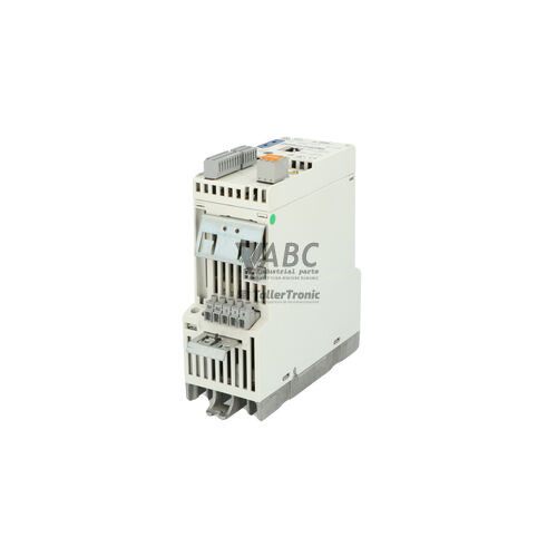
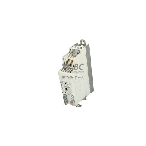
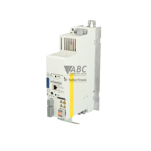
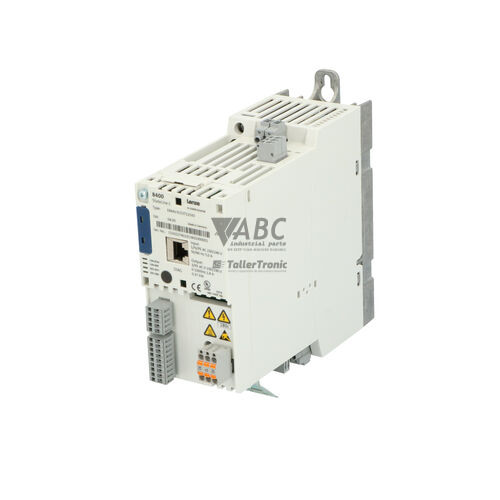
Lenze E84AVSCE2512SB0 8400 StateLine C Frequency Inverter 0.25kW



Het item werd toegevoegd aan uw offerteaanvraag
Product Information
The Lenze E84AVSCE2512SB0 is a panel-mounted frequency inverter from the L-force 8400 StateLine C series, engineered for controlled AC induction motor driving in industrial automation systems. Operating on a 230 V AC single-phase power supply with an acceptable input voltage range of 180 to 264 V AC, this compact drive provides a continuous rated output power of 0.25 kW (0.33 HP) and a rated output current of 1.7 A, with peak current capability reaching 2.55 A. Motor speed control is supported using standard V/f characteristic modes or dynamic Sensorless Vector Control (SLVC) across an output frequency range of 0 to 599 Hz at an 8 kHz switching frequency. For machinery requiring safety integration, the drive includes onboard Safe Torque Off (STO) functional safety certified up to SIL 3 according to EN IEC 62061 and PL e according to EN ISO 13849-1, allowing hardware safety shutoff without external main contactors.
Connecting and commissioning the E84AVSCE2512SB0 involves wiring physical control I/O alongside network and parameterization devices. Hardwired terminal connections include five digital inputs, one digital output, one analog input, one analog output, and one relay output. An onboard CANopen interface serves as the primary system bus, while option slots support supplementary communication modules including PROFINET (E84AYCER), PROFIBUS DP (E84AYCPM), EtherNet/IP (E84AYCEO), and EtherCAT (E84AYCET). When replacing a unit or commissioning a spare, drive parameters can be configured using the optional Lenze Keypad X400 (E84AYKCE000) or cloned directly without software using the pluggable E84AYCPM parameter memory module. Transferring this memory module from an original drive to a replacement unit instantly transfers parameter sets, application profile data, and tuning values. ABC Industrial Parts can assist with pre-configured replacement units and spare memory modules to simplify commissioning.
Diagnostics and operational monitoring are handled via four front-panel LEDs, keypad status readouts, or CANopen SDO access to the internal error history log. Dedicated DRV-READY and DRV-ERROR LEDs indicate drive enable, controller inhibit, warnings, and trip conditions, while CAN-RUN and CAN-ERR LEDs show fieldbus operational states. Common fault conditions such as output overcurrent (OC1, OC2), DC bus overvoltage (OU), undervoltage (LU), or heatsink overtemperature (OH) point to power line, wiring, or thermal issues that can be rectified in the field. Option slot communication faults (CE0) or CANopen bus errors (CE1) require checking cable termination and module seating. However, if an internal hardware fault (InF) occurs, internal circuitry or self-test routines have failed, indicating a non-field-serviceable board issue where replacing the drive or submitting the unit to ABC Industrial Parts for tested exchange or repair provides the fastest path back to production.
Technical Specifications
| Manufacturer | Lenze |
| Part Number | E84AVSCE2512SB0 |
| Model / Type | 8400 StateLine C |
| Product Family | L-force 8400 |
| Component Type | Frequency Inverter |
| Rated Power | 0.25 kW |
| Supply Voltage | 230 V AC |
| Supply Voltage Range | 180 - 264 V AC |
| Rated Output Current | 1.7 A |
| Peak Output Current | 2.55 A |
| Control Method | V/f Control / Sensorless Vector Control (SLVC) |
| Output Frequency Range | 0 - 599 Hz |
| Switching Frequency | 8 kHz |
| Digital Inputs | 5 |
| Digital Outputs | 1 |
| Analog Inputs | 1 |
| Analog Outputs | 1 |
| Relay Outputs | 1 |
| Integrated Fieldbus | CANopen |
| Mounting Type | Panel Mounting |
Programming and Configuration
The Lenze E84AVSCE2512SB0 frequency inverter utilizes a modular parameter management system centered around the pluggable Lenze E84AYCPM parameter memory module and the optional Lenze Keypad X400 (E84AYKCE000). The removable memory chip stores all customer parameter settings, motor parameters, acceleration/deceleration ramps, and terminal assignments. When replacing a failed inverter in an active production line, moving the existing E84AYCPM memory module into the replacement drive restores operational settings immediately, eliminating the need for PC software tools during field service.
Inverter operation can be parameterized for either basic V/f control for constant or variable torque loads, or high-performance Sensorless Vector Control (SLVC) for demanding speed accuracy and low-speed torque requirements. In cases where parameter set corruption occurs, indicated by fault code PEr, parameters can be reloaded using the Keypad X400, transferred from a backup parameter module, or reset to factory defaults before re-commissioning.
Communication and System Integration
System integration within standard automation architectures is facilitated by the onboard CANopen fieldbus interface on the E84AVSCE2512SB0 drive. Operating as a standard CANopen node, the inverter supports cyclic process data objects for real-time speed control and status monitoring, alongside acyclic SDO communication for parameter access and diagnostic history queries. Network status is visually confirmed on the front panel through the CAN-RUN and CAN-ERR LEDs, indicating operational, pre-operational, stopped, or bus-off states.
For integration into major industrial networks beyond CANopen, the 8400 StateLine C framework includes a dedicated option slot for fieldbus expansion modules. Supported option modules include E84AYCER for PROFINET, E84AYCPM for PROFIBUS DP, E84AYCEO for EtherNet/IP, and E84AYCET for EtherCAT. Correct shielding, module seating, and 120 Ohm termination resistors on CAN networks must be maintained to avoid communication trip codes CE0 or CE1.
Diagnostics and Status Indication
Real-time diagnostic state and trip condition monitoring on the E84AVSCE2512SB0 is provided through front-panel status LEDs and keypad diagnostic objects. The DRV-READY LED indicates power-up, controller inhibit, and operational readiness, while DRV-ERROR signals active warnings via rapid flashing or trip conditions via solid illumination. Bus states are indicated independently by the CAN-RUN and CAN-ERR LEDs. Detailed fault descriptions and error logs can be retrieved using the Keypad X400 (E84AYKCE000) or read via CANopen SDO objects.
Status LED Indicators
| LED | Color/Status | Meaning |
|---|---|---|
| DRV-READY | Green - Solid / Flashing | Solid green indicates drive is operational and ready for enable; flashing indicates controller inhibit or power-up state. |
| DRV-ERROR | Red - Solid / Flashing | Active fault or trip condition present. Fast blink indicates warning; solid or slow blink indicates active trip fault. |
| CAN-RUN | Green - Solid / Flashing | CANopen bus state: Solid ON indicates Operational; single flash indicates Pre-operational; blinking indicates Stopped. |
| CAN-ERR | Red - Solid / Flashing | CANopen communication error or bus-off condition active. |
Replacement and Spare Part Considerations
When selecting a replacement frequency inverter for a failed Lenze E84AVSCE2512SB0 unit, ensure that the power rating (0.25 kW) and input voltage specification (1-phase 230 V AC) match the existing installation. Because drive parameters are held within the removable Lenze E84AYCPM parameter memory module, swapping the module from the damaged unit directly into the spare drive transfers all machine settings instantly, minimizing downtime without requiring software tools.
If performing machine upgrades or planning long-term maintenance, Lenze offers the i550 cabinet inverter series as a recommended successor path, specifically model i55AE125B00000000S. When installing a replacement unit, ensure all integrated Safe Torque Off (STO) safety terminals are rewired and safety circuit functionality is re-tested to comply with SIL 3 / PL e requirements before putting the machine back into service.
Error Codes & Fault Codes
The following error codes may be displayed during operation or diagnostics:
| Code | Name | Description | Possible Cause | Recommended Action |
|---|---|---|---|---|
| OC1 | Short Circuit / Overcurrent | Overcurrent during acceleration or direct short circuit / earth fault on motor output terminals. | Short circuit in motor cable, earth fault in motor winding, acceleration time set too short, motor incorrectly sized. | Check motor wiring and insulation, verify motor winding resistance, increase acceleration time setting. |
| OC2 | Overcurrent during Deceleration | Overcurrent occurred during motor deceleration phase. | Deceleration time too short, braking energy too high. | Increase deceleration time, install external braking resistor if applicable. |
| OC5 | Inverter Overload / Ixt | Overload on continuous operation or frequent current spikes. | Mechanical blockage, motor undersized, duty cycle exceeded. | Check mechanical drive train for stiffness, check load profile against inverter rating. |
| OU | DC Bus Overvoltage | Voltage in DC intermediate circuit exceeded overvoltage threshold. | Excessive regenerative energy during deceleration, mains voltage too high. | Extend deceleration time, verify mains voltage, check brake chopper / brake resistor connection. |
| LU | DC Bus Undervoltage | Voltage in DC intermediate circuit dropped below minimum operating limit. | Mains supply brownout, line phase failure, power supply interruption. | Check incoming mains voltage and fuses, verify supply line quality. |
| OH | Heatsink Overtemperature | Inverter heatsink temperature exceeds limit. | Inadequate panel ventilation, cooling fan fault, ambient air temperature above specification, clogged heat sink fins. | Clean heatsink, inspect enclosure cooling/fans, reduce switching frequency or load. |
| OH4 | Motor Overtemperature | Motor temperature sensor (PTC/TK) detected motor overheating. | Motor overloaded, insufficient motor forced cooling at low speed, PTC sensor cable broken or disconnected. | Allow motor to cool down, check motor load, verify PTC sensor wiring. |
| OH7 | Internal Drive Overtemperature | Internal temperature sensor inside drive enclosure tripped. | Excessive enclosure internal temperature. | Improve enclosure cooling and airflow. |
| CE0 | Communication Error Module Slot | Communication fault with plugged option module. | Module not seated properly, option module fault, fieldbus timeout. | Power down drive, re-seat option module, verify fieldbus wiring and master configuration. |
| CE1 | CANopen Communication Error / Bus Off | CANopen communication interrupted or bus off state triggered. | Bus termination missing, loose CAN wiring, baud rate mismatch, high noise on signal lines. | Check CAN bus wiring, termination resistors (120 Ohm), baud rate settings, and shielding. |
| PEr | Parameter Set Error | Data corruption or checksum error in parameter memory module. | Power interrupted during parameter saving, corrupted memory module, incompatible parameter file. | Reload parameter set from PC, load factory defaults, or swap memory module. |
| Sd | Motor Phase Failure | One output phase to motor is open circuit. | Motor cable disconnected, contactor in output open, motor winding damaged. | Check output cable integrity, connections, motor terminal box, and output contactor status. |
| InF | Internal Hardware Fault | Internal component failure or self-test failure. | Internal electronic board defect, internal power supply fault. | Internal hardware failure — power cycle unit; if persistent, unit requires return for service or replacement. |
Frequently Asked Questions
How do I transfer drive parameters to a replacement Lenze E84AVSCE2512SB0 inverter?
Parameters can be transferred without software by swapping the pluggable E84AYCPM parameter memory module from the faulty drive into the replacement unit, or by transferring parameters using the optional Keypad X400 (E84AYKCE000).
What do the DRV-READY and DRV-ERROR LEDs indicate on the inverter?
A solid green DRV-READY LED indicates the drive is operational and ready to run, while flashing green indicates a power-up or controller inhibit state. A fast-flashing red DRV-ERROR LED signals a warning, while solid or slow-flashing red indicates an active trip fault.
Does the Lenze E84AVSCE2512SB0 frequency inverter feature integrated safety?
Yes, the inverter includes built-in Safe Torque Off (STO) functional safety certified up to SIL 3 according to EN IEC 62061 and PL e according to EN ISO 13849-1.
Which fieldbus modules can be added to the 8400 StateLine C drive slot?
The option slot accepts communication modules for PROFINET (E84AYCER), PROFIBUS DP (E84AYCPM), EtherNet/IP (E84AYCEO), and EtherCAT (E84AYCET) in addition to the standard onboard CANopen interface.
What should I do if the drive displays fault code InF?
Fault code InF indicates an internal hardware fault or board component failure. Perform a main power cycle; if the error persists, the unit contains internal board damage and requires repair or replacement.
Take advantage of our exchange formula
A defective product does not have to be worthless. At ABC Industrial Parts, you can hand in defective products and immediately benefit from a discount on your new purchase. This is a smart way to save money while contributing to a circular economy.
Play it safe with our warranty conditions
Industrial plants prefer to keep running invariably, no matter what. Therefore, it is essential that you can rely on high-quality products and/or sustainable repairs. With our warranty conditions, you can count on certainty, whether you choose new, used or repaired products.
Data backup and recovery
Have you lost valuable parameters or data due to a malfunction while the manufacturer no longer provides support? At ABC Industrial Parts, we help you secure this data, both for common and specific products.
Specific firmware and hardware versions
If you are working with specific hardware or firmware versions that are no longer available from the manufacturer, ABC Industrial Parts is your partner. When making your enquiry, clearly state which versions you need, we will then look at the possibilities of supplying those versions, so that your installations continue to function optimally.
Disclaimer:
We are not an authorised distributor of Lenze.
Product photos are for illustration purposes only and may differ from the actual product delivered.
Some of the content on this page was created with the help of AI. While we strive to provide accurate and up-to-date information, errors may occur.