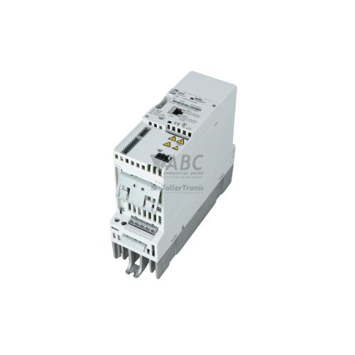
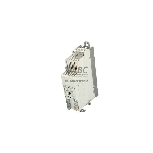
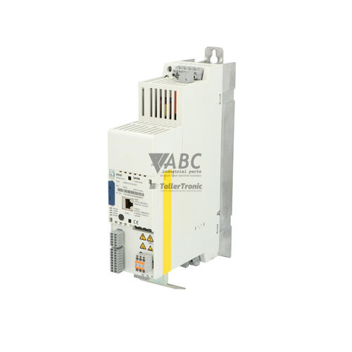
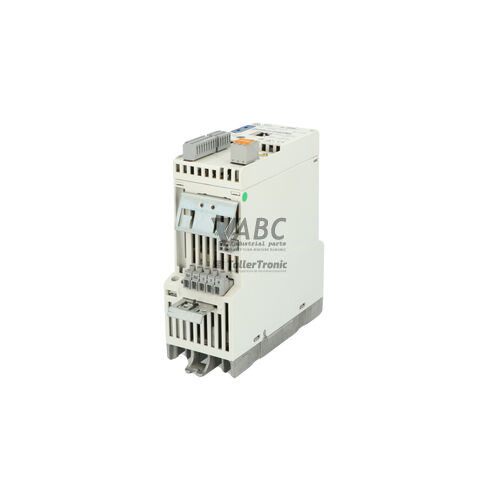
Lenze E84AVSCE7512SX0 8400 StateLine C Frequency Inverter 0.75 kW


Het item werd toegevoegd aan uw offerteaanvraag
Product Information
The Lenze E84AVSCE7512SX0 is a cabinet-mounted frequency inverter from the Lenze 8400 Series, specifically belonging to the 8400 StateLine C model family. Engineered for variable speed control of asynchronous motors up to 0.75 kW (1.0 HP), this compact IP20-rated drive operates across an input voltage range of 180 to 264 V AC at 230 V AC nominal. It supports multiple motor control modes, including V/f characteristic control, VFC open-loop vector control, and Sensorless Vector Control (SLVC), achieving a maximum output frequency of 599 Hz with an 8 kHz switching frequency. Operational features include an integrated brake chopper for dynamic braking requirements and built-in Safe Torque Off (STO) certified to EN ISO 13849-1 PL d and IEC 61508 SIL 2, allowing safe emergency stop functionality without external line contactors.
For system connection and control integration, the E84AVSCE7512SX0 incorporates a native CANopen system bus alongside a modular MCI slot designed for fieldbus expansion modules such as PROFINET (E84AYCPM) or EtherCAT (E84AYCEI). Diagnostic keypads like the Keypad X400 (E84AYKCE) connect directly through the dedicated X400 diagnostic interface. When replacing a damaged drive, commissioning does not necessarily require a full software setup if the hardware parameter memory module (Lenze Memory Module E84AYM100) is present. Transferring this pluggable module from the original drive to the replacement unit automatically restores parameter configurations, motor data, and system settings. If a memory module is unreadable or unavailable, settings must be reloaded using Lenze EASY Starter software or configured manually via the keypad. ABC Industrial Parts can support maintenance teams with verified replacement drives and parameter transfer procedures to minimize machine downtime.
Troubleshooting operational issues on the E84AVSCE7512SX0 is facilitated by front-panel status LEDs and diagnostic displays. Dual-color DRIVE status LEDs indicate operating status (green solid/flashing) and fault conditions (red solid for trips, red flashing for warnings), while dedicated CAN RUN and CAN ERR LEDs signal CANopen system bus states. Common field errors include overcurrent (OC1), earth faults (OC2), DC bus overvoltage (OU), undervoltage (LU), or STO safety circuit interruptions on terminals X6/1 and X6/2 (F-STO). First-line troubleshooting should verify mains input line stability, motor cable insulation, line termination (120 Ohm on CAN bus), and safety circuit loop continuity. When internal faults such as thermal sensor failure (OH4) or internal power unit faults (PINT) occur, the drive cannot be repaired in the field. In such instances, acquiring a fully tested replacement drive or utilizing expert exchange services through ABC Industrial Parts ensures a quick return to operational reliability.
Technical Specifications
| Manufacturer | Lenze |
| Part Number | E84AVSCE7512SX0 |
| Model / Type | 8400 StateLine C |
| Product Family | 8400 Series |
| Component Type | Frequency Inverter |
| Rated Power | 0.75 kW |
| Supply Voltage | 230 V AC |
| Supply Voltage Range | 180 - 264 V AC |
| Rated Output Current | 4 A |
| Max Output Current (60s Overload) | 6 A |
| Max Output Voltage | 230 V AC |
| Output Frequency Range | 0 - 599 Hz |
| Switching Frequency | 8 kHz |
| Control Method | V/f control, VFC open-loop vector, Sensorless Vector Control (SLVC) |
| Integrated Fieldbus | CANopen |
| Enclosure Rating | IP20 |
| Mounting Type | Cabinet installation, DIN-rail or backplate mounting |
| Integrated Safety | Safe Torque Off (STO) EN ISO 13849-1 PL d, SIL 2 (IEC 61508) |
Programming and Configuration
Drive parameterization and configuration for the Lenze E84AVSCE7512SX0 8400 StateLine C inverter are managed using Lenze EASY Starter engineering software or the optional Keypad X400 (E84AYKCE). Connected through the diagnostic X400 port, the keypad provides direct access to parameter trees, operational monitors, and fault log buffers directly on the machine floor.
The inverter utilizes the pluggable Lenze Memory Module E84AYM100 as its primary hardware memory backup. All application parameters, motor limits, I/O maps, and control modes are written to this memory module. During drive replacement, swapping the memory module into a replacement inverter transfers complete parameter profiles without requiring a PC or software connection.
Communication and System Integration
The Lenze E84AVSCE7512SX0 frequency inverter features native CANopen system bus connectivity directly on board. Dedicated front-panel LEDs for CAN RUN and CAN ERR provide real-time fieldbus diagnostic feedback, indicating pre-operational, operational, or bus-off states. Proper bus architecture requires 120 Ohm termination resistors at both physical ends of the CAN network.
To integrate into other industrial fieldbus networks, the 8400 StateLine C platform includes a modular MCI option slot. Installing an MCI PROFINET module (E84AYCPM) or MCI EtherCAT module (E84AYCEI) enables high-speed industrial Ethernet communication with higher-level PLC architectures, bypassing the need for protocol gateways.
Diagnostics and Status Indication
Comprehensive status indication on the Lenze E84AVSCE7512SX0 is provided via four status LEDs on the unit faceplate. The DRIVE status LEDs distinguish between operational states, active drive inhibition, active warnings, and hardware trips. CAN RUN and CAN ERR LEDs display fieldbus connection status and bus error conditions.
Detailed fault diagnostics are accessible by attaching a Keypad X400 or connecting EASY Starter software to access the internal error history buffer and live fault logbook. Diagnostic codes highlight distinct issue categories, differentiating between external wiring faults and internal drive failure conditions.
Status LED Indicators
| LED | Color/Status | Meaning |
|---|---|---|
| DRIVE Status (Green) | Green - Solid / Flashing | Green ON: Drive is ready / operating normally; Green flashing: Inverter active or inhibited. |
| DRIVE Status (Red) | Red - Solid / Flashing | Red flashing: Warning active; Red ON: Fault / Trip active. Indicates error condition or internal hardware fault if trip cannot be reset. |
| CAN RUN (Green) | Green - Solid / Flashing | Indicates CANopen fieldbus operational state (Pre-operational / Operational). |
| CAN ERR (Red) | Red - Solid / Flashing | Indicates CANopen fieldbus communication error / Bus OFF condition. |
Replacement and Spare Part Considerations
When replacing a Lenze E84AVSCE7512SX0 inverter, verify that the replacement unit shares the exact part number and power rating of 0.75 kW at 230 V AC. Ensure that the original Lenze Memory Module E84AYM100 is transferred to the new drive prior to applying main power to preserve parameter settings and avoid re-commissioning delays.
Pay close attention to safety circuit connections at STO terminals X6/1 and X6/2. If the STO safety function is utilized, missing 24 V power or unsynchronized safety inputs will trigger an F-STO fault and inhibit drive enable. Additionally, verify that any installed MCI communication modules (such as PROFINET or EtherCAT expansion modules) are securely seated in the replacement unit's option slot.
For long-term lifecycle planning, note that the 8400 StateLine C series has recommended successor paths within the Lenze lineup, specifically the Lenze i550 cabinet inverter platform. However, maintaining exact direct-replacement E84AVSCE7512SX0 spares remains the fastest method to avoid cabinet mechanical modifications or PLC program changes during emergency downtime events.
Error Codes & Fault Codes
The following error codes may be displayed during operation or diagnostics:
| Code | Name | Description | Possible Cause | Recommended Action |
|---|---|---|---|---|
| OC1 | Short circuit / Overcurrent | Short circuit on output terminals or excessive motor current detected. | Short circuit or ground fault in motor cable, motor winding fault, acceleration time set too short. | Check motor and motor wiring for short circuits and insulation resistance; increase acceleration ramp time. |
| OC2 | Earth fault | Earth fault current detected on motor output phase. | Ground fault in motor cabling or motor winding insulation breach. | Inspect cable shielding, insulation, and motor windings for grounding. |
| OU | Overvoltage DC bus | DC bus voltage exceeded upper limit threshold. | Regenerative energy from motor during deceleration; deceleration ramp time set too short; missing or incorrectly sized braking resistor. | Increase deceleration time ramp; check braking transistor/resistor connection and sizing. |
| LU | Undervoltage DC bus | DC bus voltage dropped below minimum operating limit. | Mains supply voltage too low, supply power failure, or transient voltage drop. | Check supply line voltage and mains supply connections. |
| OH | Heatsink overtemperature | Inverter heatsink temperature exceeded allowable threshold. | Insufficient cabinet cooling, blocked airflow/fan, ambient temperature too high, continuous drive overload. | Clean heatsink, ensure cabinet ventilation and ambient temperature are within spec, reduce continuous load. |
| OH4 | Thermal sensor failure | Internal temperature sensor error or wire break on heatsink sensor. | Internal temperature sensor defective or internal connection hardware failure. | Internal hardware fault — return unit for repair or replace inverter. |
| OH7 | Motor overtemperature | Motor temperature switch / PTC thermistor triggered. | Motor thermal overload, thermal contact tripped. | Allow motor to cool down, check motor load and cooling fan function. |
| PINT | Internal power unit fault | Hardware failure or internal communication trip between control unit and power section. | Internal power board error, corrupted internal calibration data, hardware failure. | Internal hardware fault — return unit for repair or replace inverter. |
| F-STO | Safe Torque Off active/fault | STO safety function triggered or inconsistency detected on STO input terminals. | Safety circuit open, STO terminal signals non-synchronized or missing. | Check STO safety circuit wiring and 24 V supply to STO terminals X6/1 and X6/2. |
| CE0 | CANopen communication error | CANopen system bus error or Bus OFF state. | CAN bus wire interruption, missing bus termination resistor, wrong node address or baud rate. | Check CAN bus wiring, termination resistors (120 Ohm), node ID and baud rate settings. |
| CE1 | MCI module communication fault | Communication timeout between inverter and MCI extension communication module. | MCI module missing, loose contact, or fieldbus master communication lost. | Verify seating of MCI option module and check fieldbus network cabling. |
Frequently Asked Questions
How do I transfer parameters from a failed E84AVSCE7512SX0 drive to a replacement unit?
You can transfer parameters hardware-free by removing the Lenze Memory Module E84AYM100 from the failed drive and inserting it into the replacement inverter before powering up. Alternatively, configuration files can be uploaded and downloaded via Lenze EASY Starter software using a PC adapter or Keypad X400.
What power and input voltage rating is required for the Lenze E84AVSCE7512SX0?
The Lenze E84AVSCE7512SX0 operates on single-phase or three-phase 230 V AC nominal supply voltage across a range of 180 to 264 V AC, delivering up to 0.75 kW (1.0 HP) output power and 4 A rated output current.
What does a solid red DRIVE LED mean on the inverter?
A solid red DRIVE LED indicates an active drive fault or trip state. You can check the exact error code using the Keypad X400 or EASY Starter software. If the trip cannot be reset due to internal errors like OH4 or PINT, the unit has suffered an internal hardware fault.
How is the Safe Torque Off (STO) function wired on the E84AVSCE7512SX0?
The Safe Torque Off function is wired through terminals X6/1 and X6/2. Both terminals require a synchronized 24 V supply to enable the drive output section. Opening the safety circuit triggers an F-STO fault and safely disables torque.
Can the E84AVSCE7512SX0 connect to PROFINET or EtherCAT fieldbus networks?
Yes. While the inverter includes onboard CANopen, it also features a pluggable MCI option slot that accepts modular expansion cards such as the MCI PROFINET module (E84AYCPM) or MCI EtherCAT module (E84AYCEI).
Take advantage of our exchange formula
A defective product does not have to be worthless. At ABC Industrial Parts, you can hand in defective products and immediately benefit from a discount on your new purchase. This is a smart way to save money while contributing to a circular economy.
Play it safe with our warranty conditions
Industrial plants prefer to keep running invariably, no matter what. Therefore, it is essential that you can rely on high-quality products and/or sustainable repairs. With our warranty conditions, you can count on certainty, whether you choose new, used or repaired products.
Data backup and recovery
Have you lost valuable parameters or data due to a malfunction while the manufacturer no longer provides support? At ABC Industrial Parts, we help you secure this data, both for common and specific products.
Specific firmware and hardware versions
If you are working with specific hardware or firmware versions that are no longer available from the manufacturer, ABC Industrial Parts is your partner. When making your enquiry, clearly state which versions you need, we will then look at the possibilities of supplying those versions, so that your installations continue to function optimally.
Disclaimer:
We are not an authorised distributor of Lenze.
Product photos are for illustration purposes only and may differ from the actual product delivered.
Some of the content on this page was created with the help of AI. While we strive to provide accurate and up-to-date information, errors may occur.