Lenze E94AMHE0044 9400 HighLine Multi Drive Servo Axis Module



Het item werd toegevoegd aan uw offerteaanvraag
Product Information
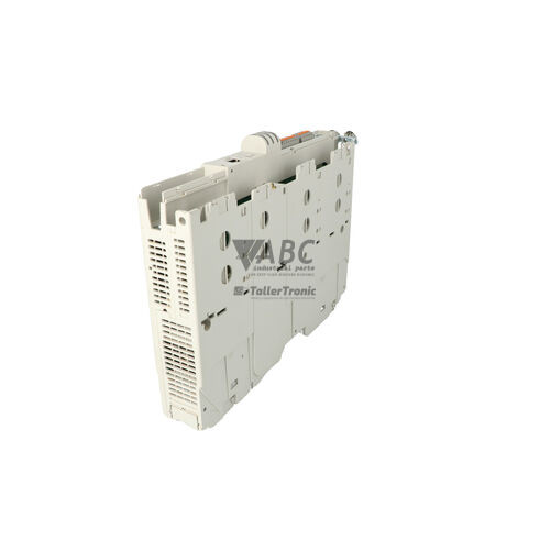
The Lenze E94AMHE0044 is a cabinet-mounted servo drive axis module within the 9400 HighLine series, designed for multi-axis motion positioning and electronic synchronization. Operating on a nominal 560 V DC bus link with an operating range of 430 V DC to 775 V DC, this drive requires a 24 V DC control supply voltage and provides a rated output power of 1.5 kW. At an 8 kHz switching frequency, it delivers a continuous output current of 4.0 A (4.4 A at 4 kHz) along with peak output current capabilities of 8.0 A for 60 seconds and 12.0 A for 3 seconds. These output characteristics allow the module to execute dynamic acceleration cycles, high-speed electronic gearing, rotary table positioning, dynamic camming, winding, and web tension control across packaging, textile, paper, and automated assembly systems.
For network integration and feedback processing, the E94AMHE0044 includes an integrated CANopen system bus alongside dual expansion option slots supporting PROFINET (E94AYCER), PROFIBUS (E94AYCPM), EtherCAT (E94AYCEI), or EtherNet/IP communication modules. Dedicated feedback connectors (X7/X8) accept standard resolvers and multi-encoder formats including SinCos, Hiperface, SSI, and TTL incremental encoders, supported by onboard digital inputs, digital outputs, and bipolar analog I/O. When commissioning a replacement unit, drive application programs, parameter records, and tuning data reside on the removable E94AYM pluggable memory module. Replacing a damaged unit can be accomplished without a programming PC by transferring the E94AYM memory card and option modules directly into the replacement chassis, with ABC Industrial Parts supplying tested replacement hardware to maintain minimal machine downtime.
System status monitoring is provided by front-panel status LEDs, including a solid green Ready LED for operational state, a red Error/Fault LED for drive trips or memory faults, and a dual-color CAN Status LED for system bus communication. Comprehensive troubleshooting is supported via the X400 diagnostic port using Lenze Engineer software, textual diagnostic messaging on the optional E94AZKAE keypad module, or direct fieldbus diagnostic registers to the master PLC. First-line diagnostics for reported trips like DC bus overvoltage (OU), undervoltage (LU), or overcurrent (OC1) should focus on checking input DC bus bar connections, braking resistors, motor isolation, and feedback cable shielding at connectors X7/X8. Unrecoverable hardware errors, such as internal self-test failures indicated by fault code H01 or continuous red LED blinking at startup, represent non-field-serviceable board defects where full module replacement or tested exchange through ABC Industrial Parts provides the fastest route back to production.
Technical Specifications
| Rated Output Power | 1.5 kW |
| Continuous Output Current (8 kHz) | 4.0 A |
| Continuous Output Current (4 kHz) | 4.4 A |
| Peak Output Current (60s) | 8.0 A |
| Peak Output Current (3s) | 12.0 A |
| Nominal DC Bus Voltage | 560 V DC |
| DC Bus Voltage Range | 430 - 775 V DC |
| Control Supply Voltage | 24 V DC |
| Digital Inputs | 8 |
| Digital Outputs | 4 |
| Analog Inputs | 2 |
| Analog Outputs | 2 |
| Switching Frequency | 8 kHz |
| Mounting Type | Cabinet / Panel Mount |
Programming and Configuration
The Lenze E94AMHE0044 servo axis module features built-in HighLine motion control technology modules that cover predefined motion profiles including electronic gearboxes, camming, and positioning. Beyond pre-configured functions, the drive supports complete custom program development in accordance with IEC 61131-3 standards. Technical personnel can access and modify internal parameters, configure task schedules, and adjust control loops using Lenze Engineer software connected via the X400 diagnostic port.
All operational software, parameter sets, and custom motion projects are stored directly on the pluggable E94AYM memory module. Because all runtime data and configuration files exist on this physical card, manual parameter extraction or software re-download is unnecessary during hardware replacement. In the event of an axis module failure, swapping the existing E94AYM card into a replacement E94AMHE0044 unit immediately restores drive parameters, motion logic, and device identity without needing an online laptop connection.
Communication and System Integration
Designed for multi-axis automation architectures, the E94AMHE0044 includes a built-in CANopen system bus interface for rapid inter-axis synchronization and control signal exchange. External communication capabilities are expanded via two modular option slots that support plug-in modules, such as E94AYCER for PROFINET, E94AYCPM for PROFIBUS, and E94AYCEI for EtherCAT, as well as EtherNet/IP options. This modular interface flexibility allows seamless integration into higher-level PLC environments and distributed control networks.
Physical connections on the drive include dedicated terminal interfaces for control power, digital, and analog signals. The module incorporates 8 digital inputs, 4 digital outputs, 2 analog inputs, and 2 analog outputs for direct machine control interaction. Motor feedback cables connect to dedicated X7 and X8 ports, offering universal evaluation for resolver devices alongside SinCos, Hiperface, SSI, and TTL incremental encoders to ensure precise position loop feedback.
Diagnostics and Status Indication
Real-time operational feedback is indicated through front-mounted LED indicators. The Ready LED illuminates solid green when the controller is enabled and operating normally. A red Error/Fault LED indicates active trips, with continuous blinking upon power-up signifying corrupted memory or internal hardware issues. The CAN Status LED displays RUN and ERR states for system bus communication monitoring.
For detailed maintenance analysis, the drive maintains a system diagnostic buffer in controller memory accessible via the X400 diagnostic port with Lenze Engineer software. Alternatively, operators can review textual diagnostic messages using the optional E94AZKAE keypad module or monitor fieldbus diagnostic registers transferred to the host controller.
Status LED Indicators
| LED | Color/Status | Meaning |
|---|---|---|
| Ready (Green) | Green - Solid | Operational state indicator. Solid green indicates controller is ready for operation / enabled. |
| Error / Fault (Red) | Red - Solid or Flashing | Fault indicator. Solid red or blinking pattern indicates drive trip or trouble condition. Continuous blinking on power-up without diagnosis connection indicates internal hardware fault or corrupted memory module. |
| CAN Status LED | Green/Red - Variable | Indicates status of integrated CAN system bus communication (RUN / ERR states). |
Replacement and Spare Part Considerations
When replacing an E94AMHE0044 axis module, ensure that the replacement hardware matches the model designation and current rating of 4.0 A at 1.5 kW output. The drive operates within a shared DC bus multi-axis system powered by Lenze 9400 Power Supply Modules (such as E94APNE or E94APRE), requiring correct DC bus bar installation and robust 24 V DC control supply connections before applying high-voltage power.
Commissioning a replacement unit is streamlined by transferring existing plug-in option modules, such as safety option cards (E94AYAE STO or E94AYAF Extended Safety) and fieldbus cards (E94AYCER, E94AYCPM, E94AYCEI). Swapping the existing E94AYM memory module into the new drive transfers all motion control programs, tuning parameters, and network settings automatically. Ensure that encoder cables on terminals X7/X8 and fieldbus wiring are properly seated and shield grounds are securely grounded to avoid communication and feedback faults.
Error Codes & Fault Codes
The following error codes may be displayed during operation or diagnostics:
| Code | Name | Description | Possible Cause | Recommended Action |
|---|---|---|---|---|
| OC1 | Short Circuit / Overcurrent | Output power stage peak current limit exceeded immediately. | Short circuit in motor cable, motor winding fault, earth fault, aggressive acceleration profile. | Check motor wiring and isolation, test motor insulation resistance, verify ramp parameters. |
| OC5 | I2t Motor Overload | Calculated motor thermal load limit exceeded. | Continuous mechanical overload, motor stalled, wrong motor current settings in parameter set. | Reduce mechanical load, check motor current rating configuration, ensure motor is turning freely. |
| OU | DC Bus Overvoltage | DC bus voltage exceeded upper limit threshold (~775 V DC). | Excessive regenerative energy during deceleration, brake chopper resistor disconnected or faulty, deceleration time too short. | Increase deceleration ramp, check brake chopper module / external braking resistor wiring and resistance value. |
| LU | DC Bus Undervoltage | DC bus voltage fell below lower threshold level. | Main AC supply failure to 9400 power supply module, power supply module fault, blown fuse in DC bus link. | Check upstream AC supply lines, DC link fuses, and DC bus bar connections between supply module and axis module. |
| OH | Heatsink Overtemperature | Power section heatsink temperature exceeded maximum safety threshold. | Insufficient cooling / ventilation, broken fan, high ambient temperature, clogged heatsink fins. | Clean heatsink, verify control cabinet fan and ventilation clearance, check internal drive fan operation. |
| OH4 | Motor Overtemperature | Thermal sensor input (KTY/PTC/TP1) reported excessive motor temperature. | Motor overloaded, cooling fan on motor failed, thermal sensor wiring broken. | Allow motor to cool down, check motor load and forced ventilation fan, check temperature sensor wiring. |
| PDR1 | Feedback Signal Fault / Encoder Fault | Encoder or resolver feedback track signal missing or corrupted. | Defective encoder cable, faulty encoder, electrical interference on feedback cable, wrong encoder feedback selection. | Inspect cable shielding and connector X7/X8, check feedback type parameterization, replace encoder cable. |
| CE0 | System Bus (CAN) Communication Failure | Communication interruption detected on integrated CAN bus interface. | Bus line disconnected, missing line termination resistor, baud rate mismatch, excessive EMC noise. | Check CAN bus cable, 120 ohm termination resistors at network ends, and node IDs. |
| F-S1 | Safety Module System Fault | Safety module detected internal safety system failure or safety input mismatch. | Faulty safety wiring, discrepancy time exceeded on dual-channel inputs, internal hardware defect on safety card. | Verify safety circuit wiring and timing. Internal hardware error: replace safety module or return drive for repair. |
| H01 | Internal Hardware Error | Self-test failure in internal processor or power supply unit. | Internal board component breakdown, corrupt firmware image. | Internal board-level failure — non-field-serviceable. Replace axis module and send defective unit for service. |
Frequently Asked Questions
How do I transfer parameters to a replacement Lenze E94AMHE0044 drive?
You can perform a zero-PC parameter transfer by moving the pluggable E94AYM memory module from the original drive into the replacement unit. The memory card stores all application logic, parameters, and tuning data.
What option modules are compatible with the E94AMHE0044 expansion slots?
The drive supports communication options including E94AYCER (PROFINET), E94AYCPM (PROFIBUS), and E94AYCEI (EtherCAT), as well as safety option modules such as E94AYAE (STO) and E94AYAF (Extended Safety).
What power supply is required to operate the E94AMHE0044 axis module?
The module operates on a shared DC bus link with a nominal voltage of 560 V DC (operating range 430 to 775 V DC), supplied by Lenze 9400 Power Supply Modules like the E94APNE or E94APRE, along with a 24 V DC control supply.
What does fault code H01 indicate on the E94AMHE0044?
Fault code H01 indicates an internal hardware error resulting from a processor or power supply self-test failure. This condition is non-field-serviceable and requires replacing the axis module or sending the unit in for repair.
Which encoder types are supported by the feedback inputs?
The X7 and X8 feedback ports support standard resolvers, SinCos, Hiperface, SSI, and TTL incremental encoders.
Take advantage of our exchange formula
A defective product does not have to be worthless. At ABC Industrial Parts, you can hand in defective products and immediately benefit from a discount on your new purchase. This is a smart way to save money while contributing to a circular economy.
Play it safe with our warranty conditions
Industrial plants prefer to keep running invariably, no matter what. Therefore, it is essential that you can rely on high-quality products and/or sustainable repairs. With our warranty conditions, you can count on certainty, whether you choose new, used or repaired products.
Data backup and recovery
Have you lost valuable parameters or data due to a malfunction while the manufacturer no longer provides support? At ABC Industrial Parts, we help you secure this data, both for common and specific products.
Specific firmware and hardware versions
If you are working with specific hardware or firmware versions that are no longer available from the manufacturer, ABC Industrial Parts is your partner. When making your enquiry, clearly state which versions you need, we will then look at the possibilities of supplying those versions, so that your installations continue to function optimally.
Disclaimer:
We are not an authorised distributor of Lenze.
Product photos are for illustration purposes only and may differ from the actual product delivered.
Some of the content on this page was created with the help of AI. While we strive to provide accurate and up-to-date information, errors may occur.