Lenze ECSEM064C4B Servo Drive Module (13350087) – Servo System ECS



Het item werd toegevoegd aan uw offerteaanvraag
Product Information
The Lenze ECSEM064C4B (ID 13350087) is a high-performance axis servo drive module belonging to the Lenze Servo System ECS product family. Designated under Function Class 'M' for Motion Control applications, this drive is engineered for multi-axis positioning, speed, and torque control in automated production machinery. Operating from a central nominal 560 V DC bus power supply, the unit provides a 400 V AC output capability delivering a continuous RMS current of 32 A and a 5-second peak current of 64 A to handle demanding acceleration profiles. Operating at an 8 kHz switching frequency, it supports 3-phase AC motors rated up to typical power outputs of 15 kW.
Integration into multi-axis machine architectures is supported through the integrated CANopen and Lenze System Bus interface, alongside an X2 interface for standard resolver feedback and an X7 interface for master frequency or SinCos encoder synchronization. An optional communication slot allows for integration into fieldbus networks using PROFIBUS-DP or EtherCAT expansion modules. Putting a spare drive module into service requires loading motor and application parameters, which are stored in the unit's non-volatile dual-parameter set EEPROM memory. Commissioning and parameter transfers can be executed using the Lenze XT Keypad (EMZ9371BC) or via Lenze Global Drive Control (GDC) and Lenze Engineer PC software connected through a Lenze EMF2177IB USB-to-CAN adapter. When replacing a failed module, ABC Industrial Parts can assist with sourcing verified replacement units or transferring stored parameter configurations to minimize machine downtime.
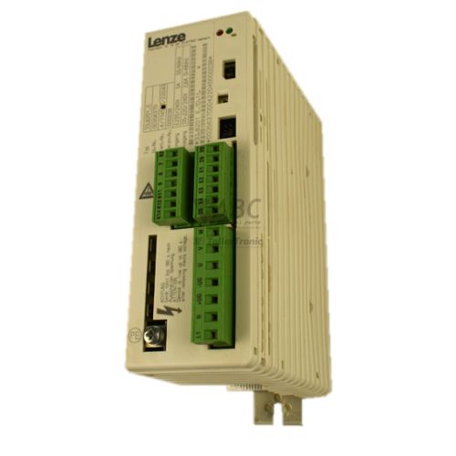
Visual status monitoring is provided by front panel LED indicators, including the green DRV-OK LED showing operational readiness or initialization status and the red DRV-ERR LED indicating active warnings or trip conditions. Detailed diagnostic codes and fault records can be accessed directly using the plug-in XT Keypad or monitored online via Lenze GDC software. Common operational faults include DC bus overvoltage (OU) or undervoltage (LU), short circuits (OC1), heatsink overtemperature (OH), and feedback communication issues (P13). First-line troubleshooting should include checking DC bus power connections from the ECSxE supply module, inspecting motor power cables and resolver/encoder wiring, and verifying bus termination resistance. Persistent red DRV-ERR indications or internal board failures such as H05 or EER point to internal hardware faults that cannot be serviced in the field, making unit replacement or repair through ABC Industrial Parts the fastest route back to production.
Technical Specifications
| Manufacturer | Lenze |
| Part Number | ECSEM064C4B |
| ID Number | 13350087 |
| Product Family | Servo System ECS |
| Function Class | Motion Control ('M') |
| DC Bus Supply Voltage | 560 V DC |
| Output Voltage Range | 400 V AC |
| Continuous Output Current | 32 A |
| Peak Output Current | 64 A (for 5 seconds) |
| Typical Motor Power Rating | 15 kW |
| Switching Frequency | 8 kHz |
| Integrated System Bus | CANopen / Lenze System Bus |
| Feedback Interfaces | X2 (Resolver), X7 (Master Frequency / SinCos Encoder) |
Programming and Configuration
The ECSEM064C4B servo drive is configured and commissioned using Lenze Global Drive Control (GDC) or Lenze Engineer software suites. Connection between a commissioning PC and the drive module is established using the Lenze EMF2177IB USB-to-CAN diagnosis adapter connected to the integrated system bus interface. Alternatively, basic parameter adjustments, monitoring, and fault interrogation can be performed directly at the machine panel using the optional Lenze XT Keypad (EMZ9371BC).
Motion parameters, motor specifications, and drive settings are retained in non-volatile onboard EEPROM memory featuring a dual parameter set architecture. This dual-memory structure allows users to store alternate application profiles or maintain a backup parameter set directly within the drive module. When installing a replacement unit, stored parameter sets can be downloaded from saved software project files or extracted from a working donor unit using GDC or Engineer software to match the original axis performance.
Communication and System Integration
Network communication and axis synchronization are handled via the integrated system bus interface supporting CANopen and Lenze System Bus protocols. This interface provides high-speed, deterministic communication between multi-axis drive modules and higher-level motion controllers. Motor feedback integration is provided through an X2 resolver input interface and an X7 multi-encoder interface capable of processing master frequency signals and SinCos encoder inputs.
For systems operating on alternative fieldbus architectures, the ECSEM064C4B includes an option slot for plug-in expansion modules. Installing these option cards enables seamless integration into industrial networks such as PROFIBUS-DP or EtherCAT. Power is supplied via a shared central DC bus topology fed by Lenze ECSxE power supply modules, optimizing energy distribution across active axes and reducing total control cabinet wiring complexity.
Diagnostics and Status Indication
Operational monitoring is provided through hardware status LEDs located on the front of the drive module as well as digital diagnostic registers readable via PC tools or keypads. The green DRV-OK LED reflects drive operational status, lighting solid when the drive is ready or active and flashing during initialization or when enabled. The red DRV-ERR LED signals fault states, flashing for warning conditions and illuminating solid when an active trip or critical hardware fault occurs.
Detailed error codes, historical fault logs, and real-time internal variables can be monitored via the plug-in XT Keypad (EMZ9371BC) or online using Lenze GDC or Lenze Engineer software. In the event of a persistent hardware error indicated by a solid red DRV-ERR LED, diagnostic software helps identify specific internal or external fault conditions to streamline field troubleshooting.
Status LED Indicators
| LED | Color/Status | Meaning |
|---|---|---|
| DRV-OK | Green - Solid / Flashing | Solid = drive ready for operation / active; Flashing = drive enabled or initializing |
| DRV-ERR | Red - Solid / Flashing | Solid = active fault/trip present; Flashing = warning present. Persistent solid red indicates an unserviceable internal hardware fault requiring repair. |
Replacement and Spare Part Considerations
When replacing an ECSEM064C4B module (ID 13350087), verify that the replacement unit shares the exact part number and Function Class 'M' designation to preserve required motion control functionality. The module operates within the Lenze Servo System ECS system and must be connected to a central DC supply module, such as the Lenze ECSxE, providing a nominal 560 V DC bus voltage.
Replacement units require parameter configuration prior to machine operation. Original motion profiles, motor feedback calibrations, and fieldbus settings must be downloaded into the module's EEPROM memory using Lenze GDC or Lenze Engineer software via the EMF2177IB USB-to-CAN adapter. Physical installation requires verifying DC bus terminal connections, checking shield termination on resolver (X2) or encoder (X7) cables, and ensuring proper 120-ohm bus termination at both ends of the CANopen network.
While legacy platforms can eventually be migrated to modern systems such as Lenze i700 or i950 servo inverters, direct replacement with a tested ECSEM064C4B module avoids costly control cabinet modifications, mechanical redesigns, and PLC program restructuring.
Error Codes & Fault Codes
The following error codes may be displayed during operation or diagnostics:
| Code | Name | Description | Possible Cause | Recommended Action |
|---|---|---|---|---|
| OC1 | Short circuit / Earth fault | Short circuit at the motor output terminals or ground/earth fault in motor cable. | Short circuit in motor wiring, motor winding fault, or short circuit in inverter power stage. | Check motor cable and motor windings for short circuits or low insulation resistance. If fault persists with motor disconnected, internal power module is defective. |
| OC2 | Earth fault | Ground fault detected on output phase. | Insulation failure in motor cable or motor stator winding. | Measure insulation resistance of motor and wiring with a megohmmeter. Check ground connection. |
| OC5 | I x t overload | Continuous overload of the drive power stage. | Drive operates above rated current limit for extended duration; mechanical blockage or undersized drive. | Check mechanical load, process parameters, acceleration time, and duty cycle. Verify drive sizing. |
| OU | Overvoltage DC bus | DC bus voltage exceeds upper threshold (>790 V DC). | Excessive regenerative energy during braking; brake chopper or braking resistor open/faulty. | Check deceleration time, evaluate braking resistor connection and power rating, verify DC bus power supply unit. |
| LU | Undervoltage DC bus | DC bus voltage fell below lower threshold. | Mains supply failure, supply module failure, or blown input fuse on supply unit. | Check mains voltage supply to the supply module (ECSxE), check DC bus interconnections and supply fuses. |
| OH | Heatsink overtemperature | Drive heatsink temperature exceeded maximum limit (>90°C). | Insufficient cabinet cooling, clogged heatsink/fan, excessive ambient temperature, or heavy overload. | Clean heatsink, verify control cabinet fan and ventilation, ensure proper clearances around drive. |
| OH4 | Motor thermal overload | Motor temperature sensor (PTC/KTY) reported overtemperature condition. | Motor overload, inadequate motor cooling, or defective thermal sensor cable. | Allow motor to cool down, check motor load and forced-cooling fan, verify temperature sensor wiring. |
| CE0 | Communication error CAN / System bus | Communication failure or timeout on integrated system bus (CAN). | Bus cable broken, improper termination resistors, heavy EMC noise, or baud rate mismatch. | Check CAN bus wiring, shielding, termination (120 Ohm at ends), and baud rate settings across nodes. |
| P13 | Encoder / Resolver error | Feedback signal error or missing encoder/resolver signal. | Encoder cable disconnected, broken wire, signal interference, or defective feedback device. | Inspect resolver/encoder cable, connectors, and screening. Verify sensor wiring layout. |
| EER | EEPROM error | Checksum fault during reading or writing non-volatile parameter memory. | Corrupted parameter memory or internal EEPROM hardware fault. | Reload factory default parameters and reconfigure. If fault remains, internal memory hardware is defective. |
| H05 | Internal hardware fault | Internal micro-controller or power board hardware failure detected during self-test. | Internal component failure on control board or driver board. | Internal hardware failure — return unit to Lenze for repair or replace module. |
Frequently Asked Questions
What software is required to configure the Lenze ECSEM064C4B servo drive?
Lenze Global Drive Control (GDC) or Lenze Engineer commissioning software is used to program and configure the ECSEM064C4B. Connecting a PC to the drive requires a Lenze EMF2177IB USB-to-CAN diagnosis adapter. Basic parameter adjustments and monitoring can also be performed using the optional Lenze XT Keypad (EMZ9371BC).
Can a replacement ECSEM064C4B drive module be installed directly without programming?
No, replacement modules require parameter configuration prior to operation. Axis parameters, motor data, and communication settings must be downloaded into the onboard EEPROM memory from a saved project backup using GDC or Engineer software.
What does a solid red DRV-ERR LED indicate on the drive?
A solid red DRV-ERR LED indicates an active trip or critical fault condition. If the red light stays solid after power cycling and disconnecting motor leads, it points to an unserviceable internal hardware fault in the control or power stage that requires module repair or replacement.
What power supply is required to run the ECSEM064C4B module?
The module operates from a central 560 V DC bus system, typically powered by a Lenze ECSxE central DC power supply module.
Which feedback devices are supported by the ECSEM064C4B?
The drive supports standard resolvers via the X2 interface as well as master frequency signals or SinCos encoders via the X7 interface.
Take advantage of our exchange formula
A defective product does not have to be worthless. At ABC Industrial Parts, you can hand in defective products and immediately benefit from a discount on your new purchase. This is a smart way to save money while contributing to a circular economy.
Play it safe with our warranty conditions
Industrial plants prefer to keep running invariably, no matter what. Therefore, it is essential that you can rely on high-quality products and/or sustainable repairs. With our warranty conditions, you can count on certainty, whether you choose new, used or repaired products.
Data backup and recovery
Have you lost valuable parameters or data due to a malfunction while the manufacturer no longer provides support? At ABC Industrial Parts, we help you secure this data, both for common and specific products.
Specific firmware and hardware versions
If you are working with specific hardware or firmware versions that are no longer available from the manufacturer, ABC Industrial Parts is your partner. When making your enquiry, clearly state which versions you need, we will then look at the possibilities of supplying those versions, so that your installations continue to function optimally.
Disclaimer:
We are not an authorised distributor of Lenze.
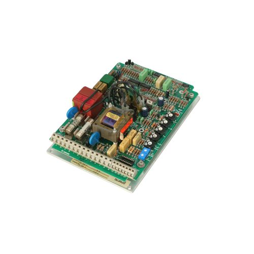
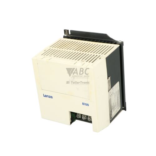
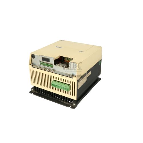
Product photos are for illustration purposes only and may differ from the actual product delivered.
Some of the content on this page was created with the help of AI. While we strive to provide accurate and up-to-date information, errors may occur.