Lust Antriebstechnik 1866-2131 VF1424L,C13,S35,PT1 Frequency Inverter


Het item werd toegevoegd aan uw offerteaanvraag
Product Information
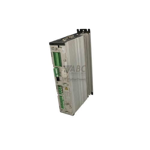
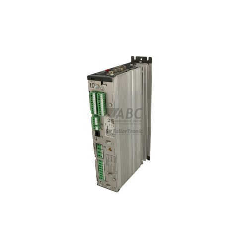
The Lust Antriebstechnik 1866-2131 (model VF1424L,C13,S35,PT1) is an 11 kW variable frequency inverter belonging to the VF1000 product family. Operating on a nominal 3-phase supply voltage from 380 V AC to 460 V AC at 50/60 Hz, the unit provides a continuous output current of 24 A and a peak current capacity of 36 A for short-term heavy overload demands. Designed for precise speed and torque regulation of 3-phase asynchronous motors, this inverter operates using sensorless vector control or V/f characteristic modes across an output frequency range of 0 to 400 Hz at a 4 kHz PWM switching frequency.
Control integration is provided through six 24 V DC digital inputs, two digital outputs, two analog inputs, and two analog outputs, combined with an integrated CANopen fieldbus interface (Option C13) supporting DS301 and DSP402 drive profiles at transmission speeds up to 1 Mbps. The Option PT1 inclusion adds dedicated evaluation inputs for motor PTC thermistors conforming to DIN 44081 and DIN 44082 to guard connected motor windings against thermal overload. When commissioning a replacement unit, parameter sets saved in internal EEPROM can be transferred using plug-in keypads such as the KP100 or KP200, or managed through DriveManager PC software versions 3.x and 4.x via the RJ45 RS-232/RS-485 interface. Technical support from ABC Industrial Parts can assist in parameter extraction and verifying hardware options prior to field installation.
Diagnostic information is indicated on the front panel via three status LEDs—READY / RUN, BUSY, and ERROR / FAULT—supplemented by numerical fault code displays on attached KP100 or KP200 keypads and diagnostic registers accessible through DriveManager software. Standard field maintenance issues such as overvoltage (E-OV), undervoltage (E-UV), or fieldbus timeouts (E-BUS) can be addressed by inspecting mains supply levels, braking resistors, or network connections. If persistent internal hardware errors such as a processor failure (E-CPU) occur, internal board components are not field-serviceable, and securing a tested replacement unit or repair through ABC Industrial Parts provides a direct route back to normal operation.
Technical Specifications
| Manufacturer | Lust Antriebstechnik |
| Part Number | 1866-2131 |
| Model / Type | VF1424L,C13,S35,PT1 |
| Product Family | VF1000 |
| Component Type | Frequency Inverter |
| Rated Power | 11 kW |
| Continuous Output Current | 24 A |
| Peak Output Current | 36 A |
| Supply Voltage Range | 380 - 460 V AC |
| Supply Frequency | 50 / 60 Hz |
| Output Voltage Range | 0 - 400 V AC |
| Maximum Output Frequency | 400 Hz |
| PWM Switching Frequency | 4 kHz |
| Digital I/O Channels | 6 Inputs / 2 Outputs |
| Analog I/O Channels | 2 Inputs / 2 Outputs |
| Fieldbus Interface | CANopen (Option C13, DS301 / DSP402) |
| Motor Thermal Protection | PTC Thermistor Evaluation (Option PT1) |
Programming and Configuration
Programming and parameter management for the Lust 1866-2131 drive are carried out using the DriveManager PC software suite (versions 3.x and 4.x) or directly via optional KP100 and KP200 plug-in operator keypads. Connection to a PC is established through the drive's RJ45 serial interface, which supports point-to-point RS-232 and multi-drop RS-485 serial communication protocols for real-time parameter tweaking and backup.
The internal architecture incorporates non-volatile EEPROM memory configured to hold up to two full parameter sets. This capability simplifies equipment setup and replacement, allowing parameter configurations to be written to memory via software or copied directly using keypads during field servicing.
Communication and System Integration
The 1866-2131 frequency inverter includes the factory-fitted Option C13 CANopen interface, allowing integration into automated fieldbus networks. It operates using standard DS301 and DSP402 communication and drive profiles, supporting high-speed control, diagnostic polling, and real-time operational data exchange at bus rates up to 1 Mbps.
Local control connections consist of six programmable 24 V DC digital inputs, two digital outputs, two analog inputs, and two analog outputs. Serial diagnostics and PC software access use an integrated RJ45 port configured for RS-232 or RS-485 physical communication interfaces.
Diagnostics and Status Indication
Drive operating status is visually presented via three front-panel LEDs, alongside numerical fault code readouts on optional KP100 or KP200 keypads. Detailed error histories, real-time diagnostic parameters, and register flags are also accessible via DriveManager PC software.
The green READY / RUN LED indicates power availability and normal operating or enabled status. The yellow BUSY LED signals active communication or parameter processing, while the red ERROR / FAULT LED illuminates continuously when an active fault condition or hardware trip occurs.
Status LED Indicators
| LED | Color/Status | Meaning |
|---|---|---|
| READY / RUN | Green - Solid / Flashing | Green LED illuminated when drive is powered and ready or operating normally; flashing indicates initialization or enable state. |
| BUSY | Yellow - Solid | Yellow LED indicates active processing, parameter transfer, or fieldbus traffic. |
| ERROR / FAULT | Red - Solid | Red LED indicates an active fault condition. A constant red light indicates internal hardware error or persistent trip condition requiring reset. |
Replacement and Spare Part Considerations
When selecting a replacement drive for part number 1866-2131, confirm that the complete designation matches VF1424L,C13,S35,PT1. The presence of Option C13 is critical for machines operating on CANopen fieldbus networks, while Option PT1 is required for applications utilizing dedicated motor PTC sensor loops.
Replacement drives must be configured with the original application parameters before normal operation can resume. Saved configurations can be loaded via DriveManager PC software or transferred directly from a previously backed-up KP100 or KP200 keypad.
Error Codes & Fault Codes
The following error codes may be displayed during operation or diagnostics:
| Code | Name | Description | Possible Cause | Recommended Action |
|---|---|---|---|---|
| E-CPU | Processor / Hardware Fault | Internal processor error, watchdog timeout, or EEPROM memory checksum fault. | Internal control board component failure, severe EMC disturbance, corrupted memory. | Perform power cycle and factory reset. If fault persists, this indicates an internal board-level failure requiring repair or unit replacement. |
| E-OC | Overcurrent | Output current exceeded internal instant overcurrent trip limit. | Short circuit or earth fault on motor terminals, acceleration time set too low, motor undersized. | Inspect motor cables and motor insulation. Increase acceleration time (ramp-up). |
| E-OV | Overvoltage | DC link bus voltage exceeded upper trip threshold. | Deceleration time too short, regenerative energy returned from motor, brake chopper/resistor missing or failed. | Increase deceleration ramp time, check braking resistor connection and resistance value. |
| E-UV | Undervoltage | DC link bus voltage dropped below minimum threshold. | Mains voltage failure, input phase drop, line fuse blown, input contactor opened. | Measure 3-phase AC supply voltage, verify input fuses and mains contactors. |
| E-OL | Motor Overload (I2t) | Motor thermal model protection threshold exceeded. | Motor operated above continuous rated load for prolonged period, mechanical restriction/jam. | Check motor mechanical load, verify rated motor parameters in drive setting. |
| E-OLI | Inverter Overload (I2t) | Power section thermal overload protection threshold reached. | Continuous operation above rated continuous drive current, ambient temperature too high. | Reduce drive load cycle, improve control cabinet ventilation. |
| E-OT | Motor Overtemperature (PTC) | Motor thermistor input (Option PT1) detected excess temperature or sensor loop break. | Motor thermal overload, insufficient motor cooling, defective or disconnected PTC sensor. | Allow motor to cool down, inspect motor cooling fan, measure resistance of PTC sensor loop. |
| E-IT | Heatsink Overtemperature | Inverter heatsink temperature sensor exceeded maximum allowed temperature. | Heatsink fan failure, clogged heatsink fins, excessive ambient temperature inside cabinet. | Clean heatsink cooling channels, inspect internal cooling fan function, verify cabinet air flow. |
| E-BUS | Fieldbus Communication Fault | CANopen fieldbus communication watchdog timer expired (Option C13). | CANbus cable disconnected, termination missing, PLC bus master stopped, baud rate mismatch. | Verify CANbus wiring, termination resistors (120 Ohm), node address, and master PLC status. |
| E-PAR | Parameter Fault | Invalid parameter combination or corrupted parameter set loaded. | Incomplete transfer of parameter file, inconsistent parameter limits. | Restore factory defaults and re-download verified parameter dataset using DriveManager. |
| E-OFF | Mains Phase Loss | Loss of one incoming phase on the 3-phase mains supply line. | Single-phase power loss, loose input terminal connection, blown line fuse. | Verify phase-to-phase voltages on incoming mains terminal block L1, L2, L3. |
Frequently Asked Questions
How are parameters backed up and transferred on the Lust 1866-2131 drive?
Parameter configurations are stored in internal EEPROM memory. They can be backed up to a PC using DriveManager software (versions 3.x/4.x) through the RJ45 serial interface or saved to a KP100/KP200 plug-in keypad module for transfer to a spare unit.
What functions do Option C13 and Option PT1 add to the inverter?
Option C13 provides an integrated CANopen fieldbus interface supporting DS301 and DSP402 profiles for PLC network communication up to 1 Mbps. Option PT1 provides direct thermistor evaluation inputs for monitoring motor PTC sensors conforming to DIN 44081 and DIN 44082.
What should be checked if an E-BUS fault appears on the display?
An E-BUS error indicates a CANopen communication watchdog timeout. Check that CANbus cabling is intact, 120 Ohm termination resistors are installed at network ends, the node address matches PLC programming, and the master PLC is running.
How should an E-CPU fault code be handled?
An E-CPU code points to an internal processor, watchdog, or memory checksum failure. Cycle input power and attempt a factory reset. If the trip persists, an internal board fault is present requiring hardware repair or unit replacement.
Take advantage of our exchange formula
A defective product does not have to be worthless. At ABC Industrial Parts, you can hand in defective products and immediately benefit from a discount on your new purchase. This is a smart way to save money while contributing to a circular economy.
Play it safe with our warranty conditions
Industrial plants prefer to keep running invariably, no matter what. Therefore, it is essential that you can rely on high-quality products and/or sustainable repairs. With our warranty conditions, you can count on certainty, whether you choose new, used or repaired products.
Data backup and recovery
Have you lost valuable parameters or data due to a malfunction while the manufacturer no longer provides support? At ABC Industrial Parts, we help you secure this data, both for common and specific products.
Specific firmware and hardware versions
If you are working with specific hardware or firmware versions that are no longer available from the manufacturer, ABC Industrial Parts is your partner. When making your enquiry, clearly state which versions you need, we will then look at the possibilities of supplying those versions, so that your installations continue to function optimally.
Disclaimer:
We are not an authorised distributor of Lust (LTI).
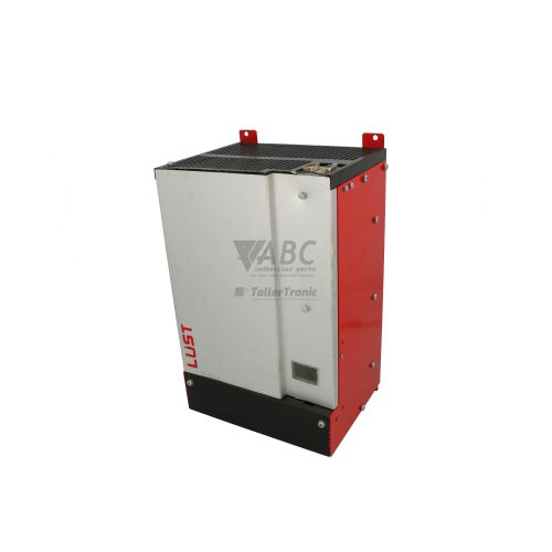
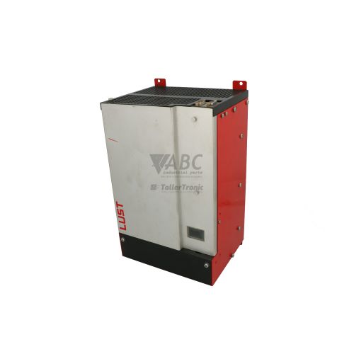
Product photos are for illustration purposes only and may differ from the actual product delivered.
Some of the content on this page was created with the help of AI. While we strive to provide accurate and up-to-date information, errors may occur.