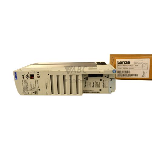
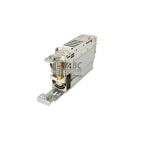
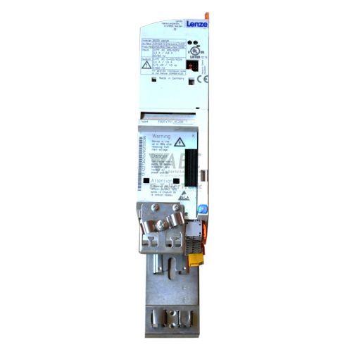
Lenze 13142236 E82EV551_4C 8200 Vector Frequency Inverter


Het item werd toegevoegd aan uw offerteaanvraag
Product Information
The Lenze 13142236, designated under model type E82EV551_4C (also referenced as E82EV551K4C), is a 0.55 kW panel-mountable frequency inverter from the Lenze 8200 Vector series. Operating across a 3-phase supply voltage range of 320 V AC to 528 V AC with a rated input current of 2.1 A, this IP20-rated AC drive provides a continuous output current of 1.8 A at 400 V AC and a maximum peak output current of 2.7 A for up to 60 seconds. Designed for precise speed and dynamic torque control, the inverter supports V/f linear, V/f quadratic, and Sensorless Vector Control (SLVC) modes with an output frequency range of 0 to 480 Hz and an 8 kHz switching frequency.
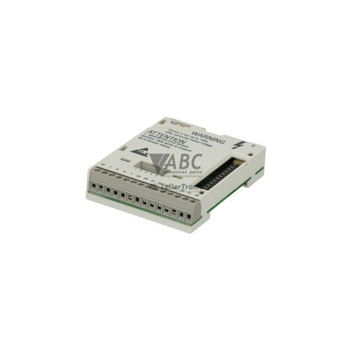
Integrating a replacement drive into an existing installation requires moving modular hardware and transferring system parameters. The unit features a modular interface slot that accepts Lenze E82ZAF series plug-in function modules for fieldbus communication over PROFIBUS-DP, CANopen, or LECOM, as well as digital and analog I/O extension. Commissioning a spare drive involves physically re-seating the plug-in function module and restoring drive configuration using the optional EMZ8201BB XT operating keypad or PC engineering software such as Lenze Global Drive Control (GDC) and Easy Starter. When parameter extraction from a faulty board is needed to copy drive settings or restore original operation, technical support from ABC Industrial Parts can help ensure smooth parameter replication.
Diagnostic oversight is provided on the front interface by status LEDs: a green LED indicates mains presence and drive ready status, while a red LED illuminates during active trip faults or blinks for alarms. Diagnostic data and the fault history memory are accessible through parameter C0161, detailing fault conditions such as DC bus undervoltage (LU), heatsink overtemperature (OH), or motor short circuit and earth faults (OC1). If motor insulation testing confirms external cabling is intact but output trips persist without a motor connected, internal power stage damage is present, making drive module replacement or a tested exchange unit from ABC Industrial Parts the effective route back to production.
Technical Specifications
| Rated Power | 0.55 kW |
| Supply Voltage Range | 320 - 528 V AC |
| Rated Input Current | 2.1 A |
| Continuous Output Current | 1.8 A |
| Max Peak Output Current | 2.7 A |
| Power Loss | 35 W |
| Output Frequency Range | 0 - 480 Hz |
| Switching Frequency | 8 kHz |
| Control Method | V/f linear, V/f quadratic, Sensorless Vector Control (SLVC) |
| Protection Rating | IP20 |
Programming and Configuration
Configuring the Lenze 13142236 E82EV551_4C frequency inverter can be performed using Lenze Global Drive Control (GDC) software, Easy Starter software, or directly via the plug-in EMZ8201BB XT operating keypad. Key operational settings include adjusting the motor continuous current limit in parameter C0087, the acceleration ramp time in parameter C0012, and the deceleration ramp time in parameter C0013.
When resolving inconsistent parameter configurations or EEPROM write errors (indicated by fault code PI), the drive can be returned to its initial default state. Setting parameter C0002 to 1 restores default factory settings in active memory, after which setting parameter C0003 to 1 permanently writes these values to the internal EEPROM prior to reconfiguring application settings.
Communication and System Integration
The modular architecture of the 8200 Vector series uses Lenze E82ZAF series plug-in function modules to integrate into industrial control networks. Depending on the selected module, the drive supports fieldbus communication via PROFIBUS-DP, CANopen, or LECOM protocols, alongside tailored digital and analog I/O expansion options.
For multi-drive panel installations, integrated terminals allow connections to a common DC bus link. Interconnecting multiple drives along a shared DC bus enables energy exchange during motor deceleration, reducing power loss and minimizing heat within the control cabinet. An integrated brake chopper is also standard, supporting rapid dynamic braking when connected to an external braking resistor.
Diagnostics and Status Indication
Drive status is indicated directly on the unit via two status LEDs. The green LED flashes when mains power is connected while the controller is inhibited, and turns solid green when the drive is enabled. The red LED remains steady during an active TRIP fault condition with impulse inhibit active, and blinks when a warning or alarm condition occurs.
Detailed diagnostic analysis can be performed using the EMZ8201BB XT keypad display, the GDC online diagnostic window, or Easy Starter monitoring tools. Fault conditions and trip events are recorded in parameter C0161, allowing maintenance technicians to inspect fault history memory during troubleshooting.
Status LED Indicators
| LED | Color/Status | Meaning |
|---|---|---|
| Green LED (DRIVE READY) | Green - Flashing or Solid | Flashing indicates mains voltage connected and controller inhibited; solid ON indicates drive is enabled and active. |
| Red LED (DRIVE FAULT) | Red - Steady or Blinking | Steady indicates active trip fault condition (impulse inhibit active); blinking indicates warning or alarm status. |
Replacement and Spare Part Considerations
When replacing a Lenze 13142236 E82EV551_4C inverter, the original plug-in function module (E82ZAF series) must be unclipped from the faulty unit and installed on the replacement drive to retain control network wiring and fieldbus addressing. Power to the drive must be isolated before removing or inserting function modules to prevent module detection errors such as code CE0.
Configuration parameters must be loaded into the replacement drive using an EMZ8201BB XT keypad or GDC engineering software to ensure ramp times, motor protection current, and control modes match the machine specification. While the 8200 Vector drive series is discontinued by the manufacturer, direct replacement spare units maintain compatibility with existing cabinet designs. For long-term facility planning, Lenze designates the i550 cabinet drive series (part number i55AE155F01000000S) as the official migration path.
Error Codes & Fault Codes
The following error codes may be displayed during operation or diagnostics:
| Code | Name | Description | Possible Cause | Recommended Action |
|---|---|---|---|---|
| C03 | System fault | Internal hardware or micro-controller software exception failure detected during operation. | Strong electromagnetic interference, hardware fault on control board. | Power cycle drive unit. If failure persists, internal hardware fault — replace the drive module. |
| CE0 | Communication error at Function Module | Communication breakdown between basic frequency inverter drive and inserted Function Module. | Function module loose or removed during operation, defective plug connector. | Check seating of plug-in function module, turn power off before re-inserting module. |
| EEr | External fault input active | External fault signal triggered via digital input assigned to TRIP function. | External fault contact opened or closed (e.g. external safety/monitoring relay). | Inspect external sensor circuit connected to external TRIP digital input. |
| LP1 | Mains phase failure | One phase missing on 3-phase AC input supply line. | Blown supply fuse, broken power cable, extreme voltage unbalance. | Check AC mains input phase voltages under load, verify line supply fuses. |
| LU | Undervoltage DC bus | Intermediate DC bus link voltage dropped below lower threshold limit (< 430 V DC). | Mains supply voltage too low, transient mains failure, input phase missing. | Check AC input supply line voltage, check input wiring and main contactors. |
| OC1 | Short circuit / Earth fault | Instantaneous short circuit or ground fault detected on output motor terminals U, V, W. | Short circuit between output motor phases, short to earth/ground, motor winding insulation broken down. | Disconnect motor cables, check motor and cabling insulation with megohmmeter. If trip persists without motor connected, internal output power stage is damaged — return for repair. |
| OC2 | Overcurrent during acceleration | Motor current exceeded maximum threshold during acceleration phase. | Acceleration ramp time (C0012) set too short, motor mechanical overload, motor dimensioned too small. | Increase acceleration time C0012, check motor sizing and mechanical load freedom. |
| OC3 | Overcurrent during deceleration | Motor current exceeded maximum threshold during braking phase. | Deceleration ramp time (C0013) set too short, high load inertia. | Increase deceleration time C0013, enable V_max controller or connect external braking resistor. |
| OC5 | Motor overload (I x t) | Continuous motor current exceeded allowable continuous thermal threshold limit. | Drive operated in continuous overload condition, mechanical machine jam/stalling. | Reduce mechanical load, verify motor continuous current setting in parameter C0087. |
| OH | Overtemperature heatsink | Inverter power stage heatsink temperature exceeded maximum safety threshold (> 90 °C). | Ambient temperature too high, cooling fins clogged with dirt, enclosure fan non-functional, insufficient panel ventilation clearance. | Clean heatsink cooling fins, check control cabinet ventilation and fan operation, increase spacing around drive. |
| OH4 | Motor overtemperature (PTC) | Motor thermistor/PTC connected to function module terminal detected motor overheating. | Motor thermal overload, insufficient motor cooling at low speeds, defective PTC thermistor sensor. | Allow motor to cool down, inspect forced ventilation blower on motor if installed, check load conditions. |
| OH7 | Overtemperature inside drive unit | Internal air temperature inside inverter housing exceeds safety limit. | Control panel ambient temperature too high (> 50 °C). | Improve cooling inside control cabinet. |
| OU | Overvoltage DC bus | Intermediate DC bus voltage exceeded maximum allowable threshold limit (> 770 V DC). | Regenerative energy from decelerating heavy load inertia too high, deceleration ramp too fast, braking resistor defective or disconnected. | Extend deceleration time C0013, check external braking resistor and connected wiring, verify brake chopper activation. |
| PI | Parameter setting error | Inconsistent or illegal parameter settings configured in internal memory. | Invalid parameter combination set or EEPROM write error. | Restore factory settings by setting parameter C0002 to 1 and burn to EEPROM (C0003 = 1). Reconfigure parameters. |
| rEr | Memory module error | Read or write error occurred when accessing parameter EEPROM or plug-in module. | Defective internal EEPROM or loose contact on memory module. | Turn off power, reseat module/keypad, power up. If persistent, replace memory/drive unit. |
Frequently Asked Questions
What engineering software is compatible with the Lenze 13142236 frequency inverter?
The inverter can be programmed and monitored using Lenze Global Drive Control (GDC) software, Easy Starter software, or locally via the EMZ8201BB XT operating keypad module.
Which communication modules can be used with the E82EV551_4C drive?
The drive features a modular slot that accepts Lenze E82ZAF series plug-in function modules, supporting CANopen, PROFIBUS-DP, LECOM, and expanded digital or analog I/O.
How do I resolve a PI fault code on the Lenze 13142236?
A PI code indicates a parameter setting error. Restore factory default settings by setting parameter C0002 to 1, then save the restored parameters to internal memory by setting parameter C0003 to 1.
What does a steady red LED indicate on the front of the drive?
A steady red LED indicates an active TRIP fault condition, meaning drive impulses are inhibited. Check parameter C0161 to identify the recorded trip cause.
What is the recommended modern replacement path for this drive?
For modernizing legacy installations, Lenze specifies the i550 cabinet drive series (part number i55AE155F01000000S) as the official successor path.
Take advantage of our exchange formula
A defective product does not have to be worthless. At ABC Industrial Parts, you can hand in defective products and immediately benefit from a discount on your new purchase. This is a smart way to save money while contributing to a circular economy.
Play it safe with our warranty conditions
Industrial plants prefer to keep running invariably, no matter what. Therefore, it is essential that you can rely on high-quality products and/or sustainable repairs. With our warranty conditions, you can count on certainty, whether you choose new, used or repaired products.
Data backup and recovery
Have you lost valuable parameters or data due to a malfunction while the manufacturer no longer provides support? At ABC Industrial Parts, we help you secure this data, both for common and specific products.
Specific firmware and hardware versions
If you are working with specific hardware or firmware versions that are no longer available from the manufacturer, ABC Industrial Parts is your partner. When making your enquiry, clearly state which versions you need, we will then look at the possibilities of supplying those versions, so that your installations continue to function optimally.
Disclaimer:
We are not an authorised distributor of Lenze.
Product photos are for illustration purposes only and may differ from the actual product delivered.
Some of the content on this page was created with the help of AI. While we strive to provide accurate and up-to-date information, errors may occur.