Lenze E93DA552I4B531 REGULATOR 9300 Servo PLC Drive Regulator



Het item werd toegevoegd aan uw offerteaanvraag
Product Information
The Lenze E93DA552I4B531 REGULATOR is an integrated 9300 Servo PLC drive controller designed for high-dynamic motion control and decentralized automation. Operating across a 3-phase AC supply voltage range of 320 V AC to 528 V AC, this 5.5 kW servo controller delivers a continuous output current of 13 A at an 8 kHz switching frequency, with a peak output capacity of 19.5 A to handle demanding acceleration phases. By integrating an IEC 61131-3 compliant soft PLC directly into the drive hardware, the unit executes local motion sequences such as electronic gearing, cam profiles, and multi-axis positioning without overburdening centralized machine controllers.
For system integration and commissioning, the E93DA552I4B531 features dedicated Sub-D connectors for resolver feedback on X7 and incremental or SinCos encoder feedback on X8, alongside 8 digital inputs, 4 digital outputs, 2 differential analog inputs, and 2 analog outputs. Real-time network integration is enabled through an integrated CANopen system bus interface and an Automation Interface (AIF) expansion slot, which accepts optional communication modules such as PROFIBUS-DP or EtherCAT. Preparing a replacement spare unit requires transferring parameter sets and PLC programs using Global Drive Control (GDC) software version 4.x or higher, Drive PLC Developer Studio (DDS) version 2.x or higher, or by cloning data directly using the removable E93DZM memory module. Technical assistance with parameter transfer or software alignment is available through ABC Industrial Parts.
Diagnostic feedback is provided on the front panel via tri-color LED indicators, including a Ready LED, Error LED, and CAN system bus LED. System state monitoring and fault analysis are further supported by a TRIP memory log accessible via an optional EMF2102IB keypad or GDC software. Active fault codes indicate specific issues such as overcurrent (OC1, OC2, OC5), DC bus overvoltage or undervoltage (OU, LU), supply phase failure (LP1), heatsink or motor thermal faults (OH, OH4), feedback signal errors on X7 or X8 (Sd2, Sd3), and communication timeouts (CE0, CE1). When internal hardware faults like EE or H05 occur, field repair is not possible, and exchanging the module or using a fully tested replacement unit from ABC Industrial Parts offers the quickest path back to full production.
Technical Specifications
| Manufacturer | Lenze |
| Part Number | E93DA552I4B531 |
| Model / Type | REGULATOR |
| Product Family | 9300 Servo PLC |
| Rated Power Output | 5.5 kW |
| Supply Voltage Range | 320 - 528 V AC |
| Continuous Output Current | 13 A |
| Peak Output Current | 19.5 A |
| Power Dissipation | 220 W |
| Switching Frequency | 8 kHz |
| Digital I/O Channels | 8 Inputs / 4 Outputs |
| Analog I/O Channels | 2 Inputs (Differential) / 2 Outputs |
| Integrated Controller | IEC 61131-3 Soft PLC |
| System Bus Interface | CANopen |
| Feedback Interfaces | Resolver (X7), Incremental / SinCos Encoder (X8) |
| Expansion Slot | Automation Interface (AIF) |
Programming and Configuration
The Lenze E93DA552I4B531 incorporates an IEC 61131-3 soft PLC directly into the drive hardware, enabling local execution of complex logic and motion control routines. Engineering and program development are performed using Drive PLC Developer Studio (DDS) version 2.x or higher, which supports standardized PLC programming languages and cyclic task configuration. System parameterization, drive commissioning, and variable tuning are managed via Global Drive Control (GDC) software version 4.x or higher.
To simplify field replacement and minimize downtime, the drive regulator utilizes a removable E93DZM memory module. This module stores complete drive parameters and compiled IEC 61131-3 user programs, allowing direct parameter and program cloning between units without requiring a PC connection. When transferring projects electronically, developers must ensure that PLC cyclic task execution limits are monitored to prevent task watchdog faults.
Communication and System Integration
Communication and system coordination across multi-axis machine setups are handled via the onboard CANopen system bus interface connected at interface X4. The CANopen link supports high-speed parameter exchange, cross-axis synchronization, electronic gearing, and cam profile processing across drive modules. Direct connectivity to engineering PCs or diagnostic software can be established using the optional EMF2177IB PC USB/CAN adapter.
The onboard Automation Interface (AIF) expansion slot provides modular flexibility for fieldbus networks. By installing option modules such as the EMF2131IB or EMF2133IB PROFIBUS-DP modules or the EMF2192IB EtherCAT module, the servo controller integrates into centralized control networks. Physical connection points include Sub-D terminal connectors for resolver feedback (X7) and encoder feedback (X8), as well as dedicated I/O terminals providing 8 digital inputs, 4 digital outputs, 2 differential analog inputs, and 2 analog outputs.
Diagnostics and Status Indication
The E93DA552I4B531 includes built-in diagnostic status LEDs and automated TRIP fault logging. Operators can view active fault history and drive status using the plug-in EMF2102IB XT Keypad or by connecting Global Drive Control (GDC) software via the CAN system bus interface or AIF slot. Real-time status registers are accessible continuously across the system bus for control system integration.
Status LED Indicators
| LED | Color/Status | Meaning |
|---|---|---|
| Ready | Green - Solid / Flashing | Continuous: drive controller operational and ready. Flashing: drive inhibit active or initialization in progress. |
| Error | Red - Solid / Flashing | Continuous: active TRIP fault present. Flashing: active warning message. |
| CAN | Green/Red - Solid / Red | Green: CAN system bus running normally. Red: bus off or communication error. |
Replacement and Spare Part Considerations
When replacing a Lenze E93DA552I4B531 drive regulator, verify that the exact part number matches the target installation. The unit operates on a 3-phase AC supply voltage of 320 V AC to 528 V AC and delivers 13 A continuous output current (5.5 kW rated power). A replacement unit must be configured with the identical parameter set and IEC 61131-3 soft PLC program as the original unit before putting it into operation.
The replacement procedure can be accelerated by physically transferring the removable E93DZM memory module from the original drive directly into the replacement regulator. If the original memory module is corrupted or missing, parameter sets and compiled applications must be uploaded using Global Drive Control (GDC) v4.x+ or Drive PLC Developer Studio (DDS) v2.x+. Ensure that any plug-in fieldbus module (such as PROFIBUS-DP or EtherCAT) installed on the AIF slot is moved to the replacement unit and that node addresses and bus termination settings are matched.
Error Codes & Fault Codes
The following error codes may be displayed during operation or diagnostics:
| Code | Name | Description | Possible Cause | Recommended Action |
|---|---|---|---|---|
| OC1 | Short circuit / Overcurrent | Short circuit or extreme overcurrent in motor output stages during acceleration. | Short circuit in motor cable, winding ground fault, motor undersized, drive acceleration ramp too short. | Check motor cable and winding insulation; increase acceleration time. |
| OC2 | Overcurrent during deceleration | Motor current exceeded limit during braking phase. | Deceleration ramp set too short, fast current limit exceeded. | Increase deceleration time; check brake chopper / braking resistor configuration. |
| OC5 | Ixt Overload | Continuous current overload monitoring triggered (Ixt overload). | Permanent mechanical overload, stalled motor shaft, drive undersized for duty cycle. | Check mechanical load and duty cycle; reduce motor load. |
| OU | Overvoltage DC bus | Intermediate circuit DC bus voltage exceeded maximum threshold. | Excessive regenerative energy during braking, braking resistor disconnected or defective, mains voltage too high. | Check external braking resistor, brake module connection, and incoming supply mains voltage. |
| LU | Undervoltage DC bus | Intermediate circuit DC bus voltage dropped below minimum operating limit. | Mains supply failure, supply phase missing, main contactor opened under load. | Check main incoming power supply, fuses, line supply cables, and power wiring. |
| LP1 | Phase failure | Missing phase on incoming 3-phase AC supply line. | Blown input fuse, loose terminal connection, asymmetrical supply line voltage. | Check main fuses, input power connections, and line phase symmetry. |
| OH | Overtemperature heatsink | Drive heatsink temperature exceeded maximum safety threshold. | Insufficient cooling airflow, dirty heatsink fins, cabinet fan failure, ambient temperature excessively high. | Clean heatsink, ensure panel fan functionality, improve enclosure ventilation. |
| OH4 | Motor temperature fault | Motor thermal sensor (PTC / KTY) reported overtemperature. | Motor overloaded, motor fan non-operational, sensor cable broken or disconnected. | Allow motor to cool down; check motor thermal sensor cable and motor load. |
| Sd2 | Resolver fault | Resolver signal connection fault or signal loss on connector X7. | Resolver cable disconnected, defective resolver shield connection, broken wire. | Check resolver feedback wiring, shielding, and Sub-D connector on X7. |
| Sd3 | Encoder fault | Incremental or Sin/Cos encoder feedback fault on connector X8. | Encoder cable defect, pulse missing, encoder supply voltage missing. | Check encoder cable, shielding, connector X8, and encoder supply voltage. |
| CE0 | AIF communication error | Communication monitoring error between drive controller and plug-in module on AIF slot. | Loose fieldbus module, fieldbus connection failure, module fault. | Verify fieldbus module seating on AIF slot; check network cabling. |
| CE1 | System bus (CAN) fault | CANbus communication error or master timeout on system bus interface X4. | Bus wiring fault, missing bus termination resistor (120 Ohm), CAN baud rate mismatch. | Check CAN bus wiring, termination resistors, and node address settings. |
| EE | EEPROM fault | Internal non-volatile memory checksum failure or read/write defect. | Defective memory module or corrupted parameter data during power down. | Internal hardware fault — reload factory parameters or replace plug-in memory module/regulator unit. |
| H05 | Internal hardware error | Hardware failure detected during power-up self-test or operation. | Internal circuit board error or damaged power section. | Internal hardware fault — field repair not possible. Return unit for repair or replace regulator. |
| P12 | PLC task watchdog fault | Drive PLC user program task processing time exceeded cyclic time limit. | Infinite loop in IEC 61131 program or PLC task execution time set too low. | Review PLC program execution time in Drive PLC Developer Studio. |
Frequently Asked Questions
What engineering software is required to configure and program the Lenze E93DA552I4B531?
Global Drive Control (GDC) software version 4.x or higher is used for parameterization and commissioning, while Drive PLC Developer Studio (DDS) version 2.x or higher is required for IEC 61131-3 soft PLC programming.
How can application programs and parameters be cloned to a spare unit?
Parameters and PLC programs can be transferred by swapping the removable E93DZM memory module directly into the replacement regulator, or by saving and restoring project files using GDC and DDS software via the CAN bus interface.
Which motor feedback devices connect to the E93DA552I4B531?
The controller features dedicated feedback connectors on the front panel: Sub-D connector X7 accepts resolver inputs, and Sub-D connector X8 supports incremental or SinCos encoders.
What optional fieldbus communication modules can be installed on the drive?
The Automation Interface (AIF) expansion slot supports optional plug-in modules including EMF2131IB or EMF2133IB for PROFIBUS-DP and EMF2192IB for EtherCAT.
What action should be taken if the regulator displays fault code H05 or EE?
Fault codes H05 and EE indicate internal hardware or memory circuit failures. These internal board faults cannot be serviced in the field and require unit repair or replacement of the drive regulator module.
Take advantage of our exchange formula
A defective product does not have to be worthless. At ABC Industrial Parts, you can hand in defective products and immediately benefit from a discount on your new purchase. This is a smart way to save money while contributing to a circular economy.
Play it safe with our warranty conditions
Industrial plants prefer to keep running invariably, no matter what. Therefore, it is essential that you can rely on high-quality products and/or sustainable repairs. With our warranty conditions, you can count on certainty, whether you choose new, used or repaired products.
Data backup and recovery
Have you lost valuable parameters or data due to a malfunction while the manufacturer no longer provides support? At ABC Industrial Parts, we help you secure this data, both for common and specific products.
Specific firmware and hardware versions
If you are working with specific hardware or firmware versions that are no longer available from the manufacturer, ABC Industrial Parts is your partner. When making your enquiry, clearly state which versions you need, we will then look at the possibilities of supplying those versions, so that your installations continue to function optimally.
Disclaimer:
We are not an authorised distributor of Lenze.
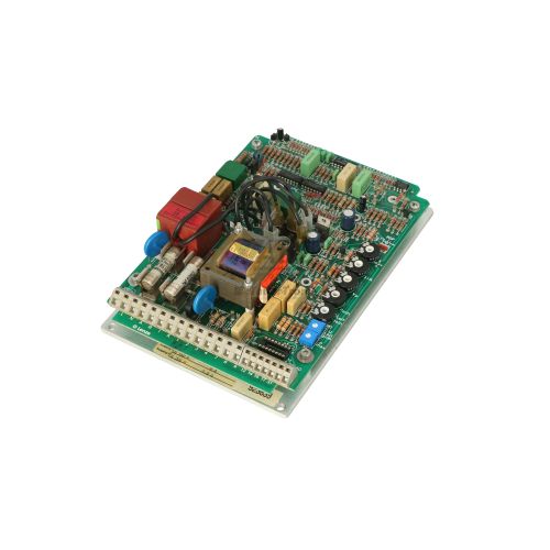
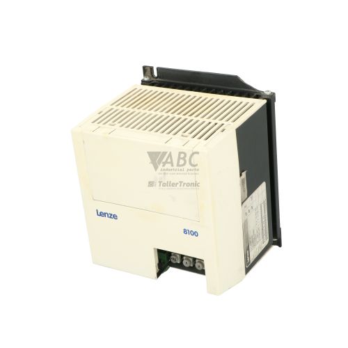
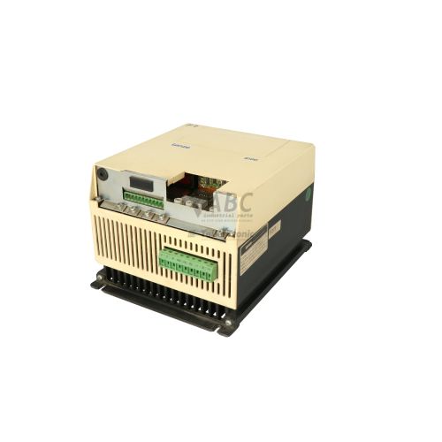
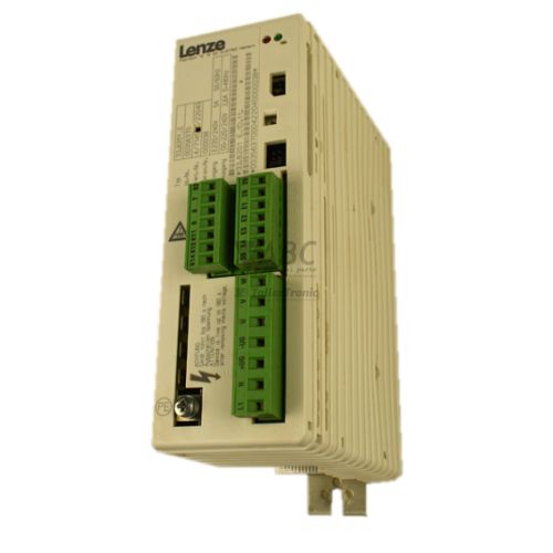
Product photos are for illustration purposes only and may differ from the actual product delivered.
Some of the content on this page was created with the help of AI. While we strive to provide accurate and up-to-date information, errors may occur.