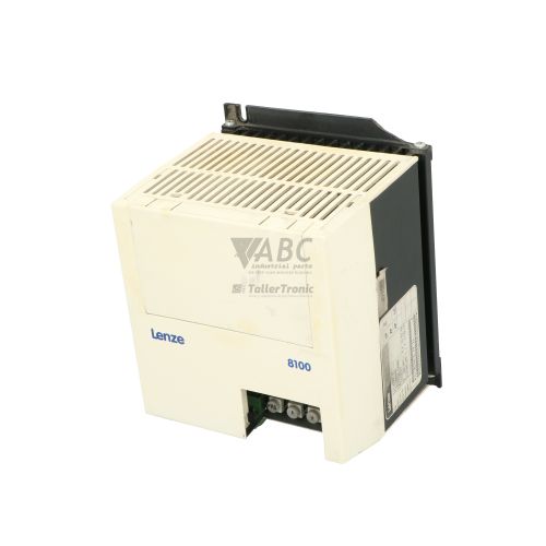
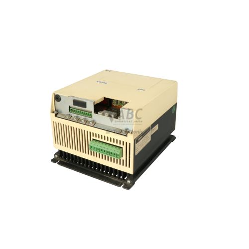
Lenze E340765-7231V40 8200 Vector Drive Base Unit V4.0


Het item werd toegevoegd aan uw offerteaanvraag
Product Information
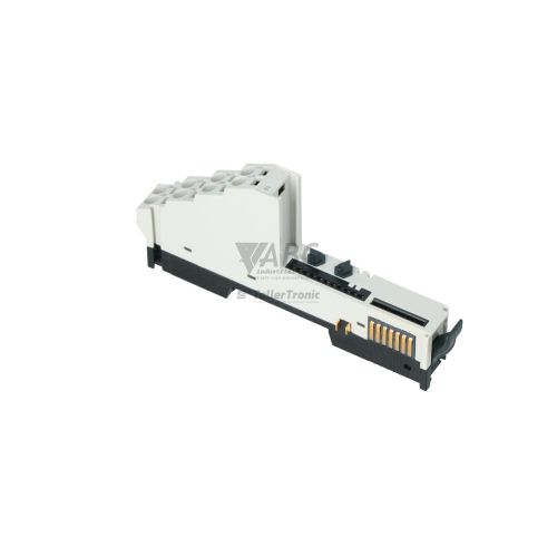
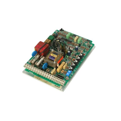
The Lenze E340765-7231V40 is an internal frequency inverter base unit assembly for the Lenze 8200 Vector series, operating on firmware version 4.0. Designed around a modular hardware architecture, this base unit houses the core power electronics processing and control digital logic. It provides dynamic regulation for three-phase AC induction motors through selectable V/f characteristic control (linear or square-law) or sensorless vector control, with adjustable carrier switching frequencies of 2 kHz, 4 kHz, 8 kHz, or 16 kHz.
Integrating a replacement base unit into existing production equipment relies on the internal multi-pin Function Module Interface (FIF) slot. This interface accepts various plug-in options, including the EMF2102IB operating keypad, standard digital and analog I/O modules, or fieldbus adapters like the EMF2133IB PROFIBUS module and EMF2171IB / EMF2172IB System Bus (CAN) modules. Commissioning a replacement requires transferring parameter data, as the unit stores up to four distinct parameter sets in non-volatile EEPROM that can be uploaded or downloaded via Lenze Global Drive Control (GDC) PC software or cloned directly using the operating keypad. ABC Industrial Parts can assist technical teams with parameter set backup extraction and spare unit setup.
System status monitoring and rapid fault diagnostics are available through onboard LED indicators, where a green LED signals operational readiness and a red LED indicates a system fault. Internal diagnostic memory buffers (accessible via parameters C0161 and C0168) log historic fault events for deep inspection using a keypad or the GDC diagnostic monitor. When non-transient error codes occur—such as internal EEPROM memory checksum failures (EE0) or hardware component degradation—board-level servicing or exchanging the damaged sub-assembly is often necessary. ABC Industrial Parts supplies tested exchange units and repair options to minimize machine downtime.
Technical Specifications
| Manufacturer | Lenze |
| Part Number | E340765-7231V40 |
| Model / Type | Base Unit |
| Component Type | Frequency Inverter |
| Product Family | 8200 Vector |
| Firmware Version | 4.0 |
| Control Method | V/f characteristic control (linear or square-law), sensorless vector control |
| Switching Frequency | 2 kHz, 4 kHz, 8 kHz, 16 kHz |
| Parameter Sets | 4 switchable internal sets |
| Module Interface | Internal Multi-pin Connector (FIF) |
| Lifecycle Status | Discontinued |
Programming and Configuration
Configuration of the Lenze E340765-7231V40 base unit is executed via Lenze Global Drive Control (GDC) software or the EMF2102IB plug-in operating keypad. The base unit integrates internal non-volatile EEPROM storage capable of retaining up to four independent, user-defined parameter sets. These parameter sets can be dynamically switched during runtime to adapt motor performance to changing application demands.
When commissioning a spare or swapped unit, engineers can download previously saved parameter files using GDC software over a PC interface or transfer saved profiles directly via the keypad memory. In instances where configuration parameters become corrupted or require a complete reset, writing a value of 1 to parameter C0002 restores the internal EEPROM back to default factory settings.
Communication and System Integration
The E340765-7231V40 base unit connects to host PLC systems and automated network architectures through its integrated Function Module Interface (FIF) multi-pin connector slot. By attaching optional plug-in modules, the base unit can be adapted to match specific fieldbus standards across production lines.
Supported communication and I/O options include the EMF2133IB PROFIBUS-DP interface, INTERBUS modules, and the EMF2171IB or EMF2172IB System Bus (CAN) modules. These adapters allow high-speed exchange of process control words, speed setpoints, torque feedback, and diagnostic data directly with central control machinery.
Diagnostics and Status Indication
The E340765-7231V40 includes primary visual status indicators directly on the unit. Solid and flashing illuminated states provide real-time feedback regarding drive operating readiness and fault conditions.
Detailed fault analysis is facilitated by an internal fault memory buffer. Historical trip events are logged under parameters C0161 and C0168, which can be read using an attached EMF2102IB keypad or via the GDC software diagnostic monitoring window.
Status LED Indicators
| LED | Color/Status | Meaning |
|---|---|---|
| Red LED | Red - Solid / Flashing | Fault/Error indicator |
| Green LED | Green - Solid / Flashing | Ready/Operation indicator |
Replacement and Spare Part Considerations
When replacing an E340765-7231V40 base unit, technicians should ensure that the replacement hardware matches the V4.0 firmware revision requirements of the host application. Because the 8200 Vector series has reached discontinued lifecycle status, utilizing direct replacement base units prevents needing to redesign control cabinet backplanes or reprogram high-level PLC drive control routines.
Before placing a replacement unit into operation, swap the plug-in Function Module (FIF) from the original drive onto the replacement base unit. Parameter sets must then be written to the new unit via the EMF2102IB keypad or downloaded using GDC software to mirror the original application's operating profile.
Error Codes & Fault Codes
The following error codes may be displayed during operation or diagnostics:
| Code | Name | Description | Possible Cause | Recommended Action |
|---|---|---|---|---|
| OC1 | Short Circuit / Overcurrent | Short circuit or extreme overcurrent at output terminals | Short circuit in motor cable, short circuit in motor, or drive output acceleration set too fast | Check motor and wiring for short circuit / earth fault; check acceleration times. |
| OC2 | Earth Fault | Ground fault detected at drive output | Ground fault in motor lead or motor winding | Check motor cable and motor insulation resistance to earth. |
| OU | DC Bus Overvoltage | Intermediate circuit voltage exceeds upper limit | Mains supply voltage too high, or motor in regenerative mode with deceleration ramp set too short | Extend deceleration time or connect a braking resistor / brake chopper. |
| LU | DC Bus Undervoltage | Intermediate circuit voltage falls below lower limit | Mains voltage too low, supply phase failure, or power loss | Check mains power supply voltage and input fuses. |
| OH | Heatsink Overtemperature | Drive heatsink temperature threshold exceeded | Inadequate cooling, ambient temperature too high, or fan failure | Improve cooling airflow, clean heatsink, or lower ambient temperature. |
| OH4 | Motor Overtemperature | Motor thermistor/PTC trip | Motor overloaded or thermal PTC sensor tripped | Check mechanical load on motor; allow motor to cool down. |
| EE0 | EEPROM Memory Error | Internal EEPROM checksum error or parameter data corrupted | Interrupted save process, power failure during parameter write, or internal board memory hardware failure | Reload factory default settings (C0002 = 1). Internal board failure requires repair or replacement if error persists. |
Frequently Asked Questions
How are parameters transferred to a replacement Lenze E340765-7231V40 base unit?
Parameters can be transferred using the plug-in EMF2102IB operating keypad or via a PC connection running Lenze Global Drive Control (GDC) software. Saved parameter sets stored in non-volatile EEPROM can be uploaded from a backup file or donor drive and downloaded directly to the replacement unit.
Which fieldbus communication modules work with the E340765-7231V40 base unit?
The base unit incorporates a multi-pin Function Module Interface (FIF) slot that supports plug-in fieldbus adapters, including the EMF2133IB PROFIBUS-DP module, EMF2171IB / EMF2172IB System Bus (CAN) modules, and INTERBUS modules.
What does an EE0 fault code indicate on this Lenze inverter unit?
An EE0 fault indicates an internal EEPROM checksum error or corrupted parameter memory, typically caused by a power interruption during a write cycle or internal memory hardware failure. Setting parameter C0002 to 1 reloads factory defaults, but persistent errors point to internal board hardware failure requiring unit repair or replacement.
What motor control modes are supported by the 8200 Vector base unit?
The E340765-7231V40 supports standard V/f characteristic control with linear or square-law curves, as well as high-performance sensorless vector control for demanding speed and torque accuracy.
Can carrier switching frequencies be modified on the E340765-7231V40?
Yes, the carrier switching frequency can be configured to 2 kHz, 4 kHz, 8 kHz, or 16 kHz, allowing engineers to optimize the balance between thermal loss and acoustic motor noise.
Take advantage of our exchange formula
A defective product does not have to be worthless. At ABC Industrial Parts, you can hand in defective products and immediately benefit from a discount on your new purchase. This is a smart way to save money while contributing to a circular economy.
Play it safe with our warranty conditions
Industrial plants prefer to keep running invariably, no matter what. Therefore, it is essential that you can rely on high-quality products and/or sustainable repairs. With our warranty conditions, you can count on certainty, whether you choose new, used or repaired products.
Data backup and recovery
Have you lost valuable parameters or data due to a malfunction while the manufacturer no longer provides support? At ABC Industrial Parts, we help you secure this data, both for common and specific products.
Specific firmware and hardware versions
If you are working with specific hardware or firmware versions that are no longer available from the manufacturer, ABC Industrial Parts is your partner. When making your enquiry, clearly state which versions you need, we will then look at the possibilities of supplying those versions, so that your installations continue to function optimally.
Disclaimer:
We are not an authorised distributor of Lenze.
Product photos are for illustration purposes only and may differ from the actual product delivered.
Some of the content on this page was created with the help of AI. While we strive to provide accurate and up-to-date information, errors may occur.