Lenze 13018342 EVF8217-E 8200 Vector Inverter 15kW 32A


Het item werd toegevoegd aan uw offerteaanvraag
Product Information
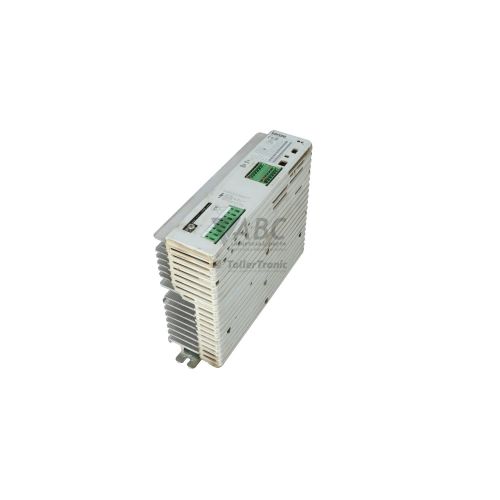
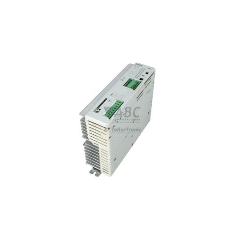
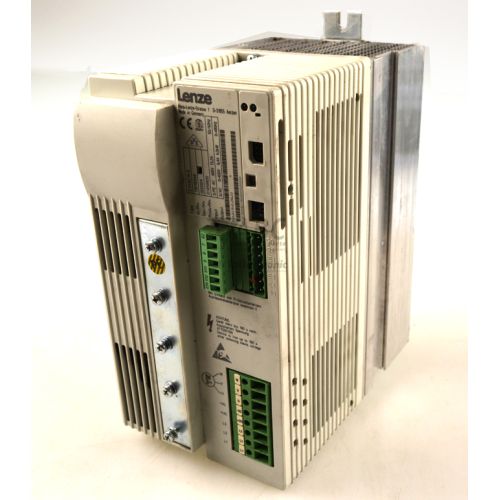
The Lenze 13018342 model EVF8217-E is a panel-mounted frequency inverter from the Lenze 8200 vector series, engineered for precise three-phase AC motor speed and torque control. Built in an E-frame enclosure with an integrated heavy-duty heatsink, this 15 kW drive operates from a 3-phase supply voltage ranging from 320 V AC to 550 V AC (nominal 3x 400/500 V AC). It delivers a continuous output current of 32 A with a 150% peak overload capacity up to 48 A for 60 seconds. Capable of driving output frequencies from 0 Hz to 480 Hz at a default switching frequency of 8 kHz, the unit supports sensorless vector control as well as linear and quadratic V/f characteristics for applications in conveyor systems, pumps, fans, packaging machinery, and machine tool spindles.
Integrating a replacement EVF8217-E drive into an automated system requires matching both power terminals and control configurations. The inverter features an integrated brake chopper transistor for direct external brake resistor connection alongside dedicated DC bus coupling terminals. Network communication and local I/O expansion are handled via a modular function slot designed for plug-in modules, such as the EMF2171IB or EMF2172IB CANopen modules, the EMF2133IB PROFIBUS-DP module, or the EMF2102IB RS-232/RS-485 serial module. When commissioning a spare drive, parameter sets must be transferred to replicate the machine profile. The internal non-volatile EEPROM holds up to four independent parameter sets, which can be configured or restored using Lenze Global Drive Control (GDC) software or the E82ZBC XT keypad display. Specialized technical support from ABC Industrial Parts can assist maintenance teams with parameter extraction or preparing donor units for rapid deployment.
Local drive status and operational warnings are indicated directly on the front panel by three LEDs: Red for active fault trips and hardware errors, Green for inverter enable and ready status, and Yellow for current limiting or active warning conditions. Diagnostics and history tracking record the four most recent fault occurrences with cause details, accessible through the E82ZBC XT keypad or GDC monitoring registers for DC bus voltage, output current, frequency, and heatsink temperature. Common field trips include mains phase failure (LP), DC bus overvoltage (OU) during deceleration, or output short circuits (OC1). When unrecoverable internal errors such as hardware faults (H05) or EEPROM memory failures (EE) occur, board-level repairs cannot be completed in the field, making a tested replacement unit or professional repair through ABC Industrial Parts the optimal pathway back to production.
Technical Specifications
| Manufacturer | Lenze |
| Part number | 13018342 |
| Model / type | EVF8217-E |
| Product family | 8200 vector |
| Component type | Frequency Inverter |
| Rated power | 15 kW |
| Nominal supply voltage | 3x 400/500 V AC |
| Supply voltage range | 320 - 550 V AC |
| Continuous output current | 32 A |
| Maximum output current | 48 A (for 60 seconds) |
| Output frequency range | 0 - 480 Hz |
| Default switching frequency | 8 kHz |
| Control modes | Sensorless vector control / V/f linear / V/f quadratic |
| Mounting type | Panel mounting (E design with integrated heatsink) |
| Brake transistor | Integrated |
Programming and Configuration
Programming and configuring the Lenze 13018342 EVF8217-E inverter is performed using Lenze Global Drive Control (GDC) software or the detachable E82ZBC XT keypad display. GDC software connects via a PC interface to offer complete parameter access, diagnostic parameter logging, and operational monitoring. For direct panel-side commissioning, the E82ZBC XT keypad allows operators to navigate the parameter menu, alter drive parameters, view real-time feedback values, and clear active trip states.
The inverter contains internal non-volatile EEPROM memory capable of holding up to four complete parameter datasets (datasets 1 through 4). This multi-dataset architecture allows users to program different operating profiles or keep complete backup sets stored directly on the drive. To prevent parameter corruption during saving operations, stable control logic power must be maintained. If parameter errors (Pr) arise due to interrupted dataset writes, reloading factory default settings via code C0002 = 1 restores baseline drive parameters before reloading valid application datasets.
Communication and System Integration
The Lenze 8200 vector series utilizes a modular hardware design that separates the main power structure from control and fieldbus communications. The EVF8217-E unit includes a built-in functional module slot designed to accept specialized communication adapters, allowing seamless integration into fieldbus networks without modifying the underlying inverter hardware.
Compatible plug-in function modules include the EMF2171IB and EMF2172IB CANopen modules, the EMF2133IB PROFIBUS-DP module, and the EMF2102IB RS-232/RS-485 module, along with INTERBUS and LECOM options. In addition to option slot communications, the drive provides dedicated terminals for 3-phase main AC power input (L1, L2, L3), motor power output (U, V, W), external brake resistor connection via the integrated brake chopper, and DC bus terminals for shared DC link configurations.
Diagnostics and Status Indication
Operational monitoring for the EVF8217-E drive is conducted via three status LEDs located on the unit, alongside software and keypad monitoring tools. Real-time values such as output frequency, motor current, DC bus voltage, and drive heatsink temperature can be tracked continuously through Lenze Global Drive Control (GDC) software or the E82ZBC XT keypad. An internal fault history memory logs the last four fault events together with recorded cause data to support fast root-cause evaluation.
Status LED Indicators
| LED | Color/Status | Meaning |
|---|---|---|
| Red (Fault/Error) | Red - Solid or Flashing | Flashing indicates an active fault trip; Solid indicates an internal trip or hardware error. |
| Green (Ready/Operation) | Green - Solid or Flashing | Solid indicates inverter enabled and motor running; Flashing indicates inverter ready or pulse inhibit active. |
| Yellow (Limit/Warning) | Yellow - Solid or Flashing | Indicates current limit reached or an active warning condition. |
Replacement and Spare Part Considerations
Replacing a Lenze 13018342 EVF8217-E requires verifying power characteristics and option module compatibility. Ensure the spare unit matches the 15 kW power rating, 32 A output current capacity, and physical panel mounting footprint. When swapping units, transfer the installed function module (such as PROFIBUS, CANopen, or RS-232/RS-485) from the existing inverter into the replacement unit's slot, ensuring the module is fully seated and secured to avoid communication faults (CE0).
Before placing a replacement inverter into operational service, parameter settings matching the machine must be restored into the internal EEPROM using GDC software or an E82ZBC XT keypad display. For systems undergoing broader panel modernizations where the 8200 vector series is being updated, standard migration pathways exist to current Lenze drive families, including the Lenze 8400 StateLine, 8400 HighLine, or i550 series inverters.
Error Codes & Fault Codes
The following error codes may be displayed during operation or diagnostics:
| Code | Name | Description | Possible Cause | Recommended Action |
|---|---|---|---|---|
| OC1 | Short Circuit | Short circuit at inverter output or Earth fault | Short circuit in motor cable, winding short circuit, excessive motor cable length, or earth fault | Check motor cable for phase-to-phase and phase-to-ground short circuits. Check motor windings with megohmmeter. Inspect power module; if short circuit persists with motor disconnected, internal power section is damaged (return unit for repair). |
| OC2 | Earth Fault | Earth fault / ground fault detected at output phase | Ground fault in motor lead or motor frame, insulation degradation | Check motor insulation and motor cable shielding/grounding. If fault persists with cable disconnected, unit requires hardware repair. |
| OC5 | I x t Overload | Drive overloaded continuously in I x t thermal accumulation zone | Mechanical overload, drive undersized for acceleration profile, machine stall | Reduce mechanical load, extend acceleration time, or check motor parameters. |
| OU | Overvoltage DC Bus | DC bus voltage exceeded maximum threshold limit (> 770 V DC / 800 V DC) | Regenerative motor energy during deceleration with deceleration time set too short, missing or defective brake resistor, or brake chopper fault | Extend deceleration time (ramp-down time), verify external brake resistor connection and resistance value, check internal brake chopper operation. |
| LU | Undervoltage DC Bus | DC bus voltage dropped below minimum operating limit (< 400 V DC on 400V units) | Mains supply voltage drop, phase loss, blown input fuse, peak load on supply line | Measure line input AC supply voltage across all three phases. Check input fuses and supply contactor. |
| OH | Overtemperature Heatsink | Inverter heatsink temperature exceeded maximum permissible limit | Dirty/clogged heatsink fins, defective cooling fan, ambient temperature too high, insufficient cabinet ventilation | Clean heatsink, inspect internal fan rotation, improve panel ventilation. |
| OH4 | Motor Overtemperature (PTC) | Motor PTC / thermal sensor tripped on terminal threshold | Motor thermal overload, blocked motor cooling, defective motor sensor or cable break | Allow motor to cool down, inspect motor fan/cooling, check PTC resistance and wiring at control terminals. |
| LP | Mains Phase Failure | One of the three AC input supply phases is missing or severely unbalanced | Blown line fuse, loose power terminal connection, unstable AC main supply line | Check line supply voltages under load on input terminals L1, L2, L3. Inspect fuses and main contactor contacts. |
| Pr | Parameter Error | Checksum or parameter data error in active parameter set | Interrupted parameter transfer, electrical noise during non-volatile save, EEPROM data corruption | Reload factory default settings (C0002 = 1) and reload dataset from backup. |
| EE | EEPROM Memory Error | Hardware fault in internal EEPROM non-volatile memory chip | EEPROM hardware component failure, repeated writing limit exceeded | Attempt factory reset. If error persists, internal control board is defective — replace the drive unit or return for service. |
| H05 | Internal Hardware Error | Control board hardware detection fault | Unrecoverable internal microprocessor or gate driver hardware fault | Cycle logic power. If fault re-occurs, internal board fault — non-field-serviceable; replace unit or return for repair. |
| CE0 | Communication Failure | Communication breakdown between inverter control unit and installed function module | Function module loose or unseated, bus line noise, module component failure | Re-seat function module in slot, verify screw connection, check shielding. |
Frequently Asked Questions
What engineering software is required to configure the Lenze EVF8217-E drive?
The EVF8217-E inverter is programmed and configured using Lenze Global Drive Control (GDC) software. Keypad navigation and parameter adjustments can also be performed directly on the unit using an E82ZBC XT keypad display.
How are drive parameter sets backed up and transferred to a replacement EVF8217-E?
Parameter datasets can be backed up and transferred using Lenze Global Drive Control (GDC) software connected via a PC interface, or copied directly into the internal EEPROM memory using the plug-in E82ZBC XT keypad display.
Which fieldbus communication networks can be integrated with this drive?
The EVF8217-E supports fieldbus communication through plug-in option modules, including the EMF2171IB and EMF2172IB CANopen modules, EMF2133IB PROFIBUS-DP module, EMF2102IB RS-232/RS-485 module, as well as INTERBUS and LECOM modules.
What does an OC1 fault code indicate on the EVF8217-E inverter?
An OC1 fault code indicates an output short circuit or earth fault. It is caused by motor winding shorts, cable short circuits, excessive cable length, or ground faults. If OC1 remains active with the motor leads disconnected, internal power module damage is present.
Which Lenze drive series serve as successor replacements for the EVF8217-E?
Direct replacement and migration pathways for the 8200 vector series include the Lenze 8400 StateLine, Lenze 8400 HighLine, or Lenze i550 inverter series.
Take advantage of our exchange formula
A defective product does not have to be worthless. At ABC Industrial Parts, you can hand in defective products and immediately benefit from a discount on your new purchase. This is a smart way to save money while contributing to a circular economy.
Play it safe with our warranty conditions
Industrial plants prefer to keep running invariably, no matter what. Therefore, it is essential that you can rely on high-quality products and/or sustainable repairs. With our warranty conditions, you can count on certainty, whether you choose new, used or repaired products.
Data backup and recovery
Have you lost valuable parameters or data due to a malfunction while the manufacturer no longer provides support? At ABC Industrial Parts, we help you secure this data, both for common and specific products.
Specific firmware and hardware versions
If you are working with specific hardware or firmware versions that are no longer available from the manufacturer, ABC Industrial Parts is your partner. When making your enquiry, clearly state which versions you need, we will then look at the possibilities of supplying those versions, so that your installations continue to function optimally.
Disclaimer:
We are not an authorised distributor of Lenze.
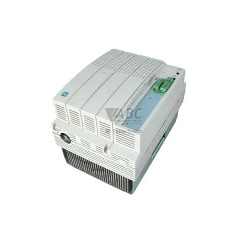
Product photos are for illustration purposes only and may differ from the actual product delivered.
Some of the content on this page was created with the help of AI. While we strive to provide accurate and up-to-date information, errors may occur.