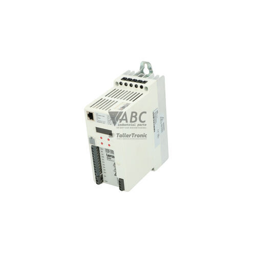
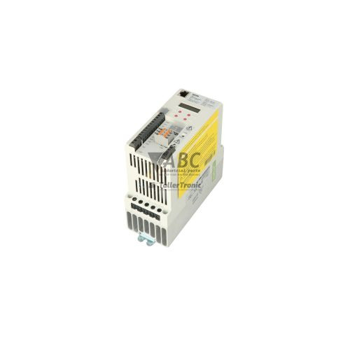
Lenze 13466008 E84AVBDE7512SX0 8400 Baseline Inverter 0.75kW


Het item werd toegevoegd aan uw offerteaanvraag
Product Information
The Lenze 13466008, designated by model code E84AVBDE7512SX0, is a cabinet-mounted 0.75 kW (1.0 HP) variable frequency inverter within the Lenze 8400 Baseline family. Designed for precise speed control of standard asynchronous electric motors in industrial automation, this unit operates across a 3-phase mains supply voltage range of 320 V AC to 552 V AC (400 V / 480 V AC nominal) at 45 to 65 Hz. The inverter delivers a rated output current of 2.4 A with a peak output of 3.6 A and supports linear V/f, quadratic V/f, and Vector Frequency Control (VFC) modes. Equipped with an integrated Class C2/Class A EMC filter compliant with EN 61800-3, the SX0 variant provides efficient motor driving without requiring external line filtering, though it does not include an internal braking chopper.
Integrating this drive into an existing control cabinet relies on its built-in CANopen system bus interface alongside flexible physical terminal control. Physical control connections include 4 digital inputs, 1 configurable analog input supporting 0–10 V, 0–20 mA, or 4–20 mA, 1 digital output, and 1 relay changeover contact rated for 250 V AC at 3 A. Parameterization and commissioning can be managed using Lenze EASY Starter or L-force Engineer software (version 2.12 or higher) via the E84AVZCD000 USB diagnostic adapter, or directly through an optional E84AVZKE000 Keypad X400. Complete parameter sets are stored on a pluggable E84AYM10S memory module, enabling zero-tool parameter extraction and transfer during drive replacement so a spare unit can be commissioned quickly without software tools. Technical support from ABC Industrial Parts can assist when swapping drives or verifying configuration compatibility across machine control systems.
Diagnostic feedback is provided on the front panel by dedicated LEDs for drive status (DRV-READY and DRV-ERR) and fieldbus state (CAN-RUN and CAN-ERR). Fault events such as output short circuits (OC1), overvoltage conditions (OU), line undervoltage (LU), or heatsink overtemperature (OH) generate trip conditions that can be evaluated via keypad, fieldbus status registers, or diagnostic software. While parameter memory errors (PEr) or line supply faults can usually be corrected through wiring adjustments or parameter reloads, error codes like PI indicate internal power stage or gate driver hardware failures. Internal hardware defects cannot be repaired on site, making a tested replacement drive or repair service from ABC Industrial Parts the most reliable path to restore production operations.
Technical Specifications
| Rated Power | 0.75 kW |
| Supply Voltage | 3 AC 400/480 V AC |
| Supply Voltage Range | 320 - 552 V AC |
| Supply Frequency | 45 - 65 Hz |
| Rated Output Current | 2.4 A |
| Maximum Output Current | 3.6 A |
| Output Voltage Range | 0 - Mains Voltage V AC |
| Output Frequency Range | 0 - 580 Hz |
| Switching Frequency | 8 kHz |
| Control Method | V/f Characteristic, VFC Vector Frequency Control |
| Digital Inputs | 4 |
| Digital Outputs | 1 |
| Analog Inputs | 1 |
| Relay Outputs | 1 |
| Integrated EMC Filter | Class C2 / Class A (EN 61800-3) |
| Integrated Brake Chopper | No |
Programming and Configuration
Configuring the Lenze 13466008 inverter is achieved through Lenze engineering software suites, specifically L-force Engineer (version 2.12 or higher) and Lenze EASY Starter. PC connectivity is established using the optional Lenze USB Diagnostic Adapter (E84AVZCD000), which connects directly to the drive interface for real-time monitoring, parameter adjustment, and oscilloscope function diagnostics. Alternatively, local parameterization, operation, and manual override can be performed at the cabinet door or unit front using the Lenze Keypad X400 (E84AVZKE000).
A key feature of the drive's parameter storage architecture is the removable E84AYM10S EEPROM memory module. All operational parameters, motor characterization data, ramp times, and I/O assignments reside directly on this pluggable module. During commissioning or maintenance, parameter sets can be written from engineering software to the module or copied between drives. In the event of an inverter swap, transferring the pluggable EEPROM directly to the replacement unit eliminates the need for software programming tools or field re-commissioning.
Communication and System Integration
The E84AVBDE7512SX0 frequency inverter features an integrated CANopen fieldbus interface as standard, enabling direct connection to industrial motion controllers and PLCs without additional expansion cards. Supporting transmission rates up to 1 Mbit/s, the CANopen bus provides real-time access to control words, setpoints, output frequencies, actual motor currents, and drive status registers. Node addressing and baud rate selection are configured via hardware DIP switches or software settings, with bus activity indicated on the front panel.
For hardwired control schemes, the drive provides a practical array of control terminals. Inputs consist of 4 digital inputs for run, stop, and direction commands, plus 1 configurable analog input accepting 0–10 V, 0–20 mA, or 4–20 mA setpoint signals. Digital outputs include 1 programmable digital output and 1 changeover relay contact rated up to 250 V AC and 3 A for operational readiness or fault signaling. An integrated Class C2/Class A EMC interference filter according to EN 61800-3 suppresses conducted high-frequency disturbances, maintaining electromagnetic compatibility within standard industrial control panels.
Diagnostics and Status Indication
System health and network statuses are displayed via four status LEDs on the front panel of the inverter. Two LEDs monitor general drive behavior: DRV-READY (green) indicates operational states such as active running or standby, while DRV-ERR (red) signals warning conditions or active trips. Two additional LEDs, CAN-RUN (green) and CAN-ERR (red), provide immediate status for the CANopen network, highlighting operational states, pre-operational modes, frame errors, or bus-off conditions.
In addition to visual LED indications, comprehensive diagnostic tools allow detailed fault interrogation. Keypad X400 and connected PC software tools access an internal fault history log containing timestamps and operating parameters recorded during trip events. Fieldbus master controllers can also query internal status registers continuously over CANopen to monitor operational health and detect system warnings prior to drive shutdown.
Status LED Indicators
| LED | Color/Status | Meaning |
|---|---|---|
| DRV-READY | Green - Solid / Flashing / Off | Green LED indicates drive operational state. Solid green = drive active/running; Flashing green = drive ready/standby. Off = power supply missing or internal fault. |
| DRV-ERR | Red - Solid / Flashing | Red LED indicates fault condition. Solid red = fault active (drive tripped); Flashing red = warning state active. If solid red persists after fault reset attempts, indicates internal power board / control unit hardware fault. |
| CAN-RUN | Green - Solid / Flashing / Single flash | Green LED indicates CANopen state. Solid green = Operational state; Flashing green = Pre-operational state; Single flash = Stopped state. |
| CAN-ERR | Red - Solid / Flashing | Red LED indicates CANopen communication errors. Flashing red = Bus warning / frame errors; Solid red = CAN Bus Off condition. |
Replacement and Spare Part Considerations
When replacing a Lenze 13466008 inverter (model E84AVBDE7512SX0), it is important to confirm exact model designations and drive options. The SX0 designation specifies a unit built without an integrated braking chopper. If the application involves dynamic braking or active regenerative loads requiring a braking resistor, the SX0 variant will trigger DC bus overvoltage faults (OU); such applications require the SB0 variant (E84AVBDE7512SB0).
Drive replacement is simplified by the removable E84AYM10S memory module. Powering down the unit and transferring the original memory module to the replacement drive restores all configured motor data, ramp settings, and fieldbus parameters instantly upon power-up. Note that while Lenze discontinued the 8400 Baseline product family in March 2020, migration to the successor Lenze i550 series is possible, though standard replacement with a matching 8400 Baseline unit avoids control panel rewiring or PLC program adjustments.
Error Codes & Fault Codes
The following error codes may be displayed during operation or diagnostics:
| Code | Name | Description | Possible Cause | Recommended Action |
|---|---|---|---|---|
| OC1 | Short circuit / Overcurrent motor output | Instantaneous short circuit or severe overcurrent detected at inverter output power terminals. | Short circuit between motor phase conductors or ground fault in motor lead wire; motor cable excessively long; acceleration ramp time configured too short; improper motor model parameterization. | Check motor winding insulation and power cable for short circuits; increase acceleration time parameter (C00012); verify correct motor parameters. |
| OC2 | Overcurrent during acceleration | Output current limit exceeded while accelerating motor speed. | Acceleration time too fast for connected mechanical load inertia; mechanical jam or binding; undersized motor/inverter combination. | Increase acceleration time (C00012); check mechanical drive train for binding or overload; review motor parameters. |
| OC5 | Ground fault / Earth fault | Ground fault current detected on motor output phases. | Insulation damage in motor stator winding or motor power cable to earth ground; high capacitive line-to-ground leakage current. | Perform insulation resistance test (megger) on motor and cable; inspect cable connections; reduce switching frequency. |
| OU | DC bus overvoltage | DC bus voltage exceeded upper limit threshold (approx. 770 V DC). | Regenerative energy fed back from motor during deceleration; deceleration ramp time too fast; incoming line voltage spike. Note: Model E84AVBDE7512SX0 lacks an integrated braking chopper. | Extend deceleration time parameter (C00013); check AC mains line voltage; if load is strongly regenerative, a unit variant with braking chopper (E84AVBDE7512SB0) is required. |
| LU | DC bus undervoltage | DC bus voltage fell below minimum allowable operating threshold. | Mains supply line voltage too low or interrupted; single-phase loss on 3-phase mains input; loose supply line wiring connection or blown line fuse. | Measure input voltage across all three mains phases; check line fuses and power wiring terminals. |
| OH | Heatsink overtemperature | Inverter heatsink temperature exceeded maximum operating limit. | Inadequate cooling airflow inside enclosure; ambient air temperature above 45°C/55°C limit; heatsink cooling fins dirty or blocked; continuous overload operation. | Clean heatsink cooling fins; verify enclosure fan operation; improve cabinet ventilation; reduce inverter switching frequency or motor load. |
| OH4 | Motor overtemperature (I2t thermal model) | Calculated motor thermal overload limit reached. | Continuous motor operation above rated motor current; prolonged low-speed operation under heavy load without forced motor cooling fan. | Allow motor to cool down; check motor application for mechanical overload; install forced ventilation fan on motor if operating continuously at low RPM. |
| CE0 | CANopen communication fault | CANopen bus off error or communication time-out. | Broken or disconnected CANbus wire; incorrect node address DIP switch settings; missing 120-ohm bus termination resistor; baud rate mismatch. | Inspect CAN wiring and connectors; check DIP switches for node ID and baud rate; ensure termination resistors are active at both bus ends. |
| PEr | Parameter memory fault | Checksum or transfer error when accessing memory module E84AYM10S. | Memory module missing, unseated, or damaged; power interrupted while saving parameters. | Verify memory module is seated firmly in its slot; attempt to reload default factory parameters; replace memory module if unrecoverable. |
| PI | Power section hardware fault | Internal error in drive power stage or gate driver circuit. | Internal electronic power component defect or damaged IGBT module. | Internal hardware fault — non-serviceable in field. Replace the frequency inverter unit. |
Frequently Asked Questions
What is the procedure for transferring parameters when replacing a Lenze 13466008 inverter?
Parameter transfer can be accomplished without software tools by powering off the drive and moving the pluggable E84AYM10S EEPROM memory module from the original drive directly into the replacement drive. All motor parameters, I/O settings, and CANopen node configurations are retained on the module.
What software is required to program and diagnose the Lenze E84AVBDE7512SX0?
Programming and diagnosis can be performed using Lenze EASY Starter or Lenze L-force Engineer software (version 2.12 or higher). Connecting a PC to the drive requires the optional Lenze USB Diagnostic Adapter (E84AVZCD000).
Does the E84AVBDE7512SX0 model support dynamic braking with an external resistor?
No. The SX0 designation indicates that this specific model does not include an integrated braking chopper. Applications requiring regenerative braking require a model variant equipped with a brake chopper, such as E84AVBDE7512SB0.
What do the status LEDs on the front panel of the E84AVBDE7512SX0 indicate?
The green DRV-READY LED indicates power and operating state (solid green for active/running, flashing for ready/standby). The red DRV-ERR LED indicates fault conditions (solid red for active trip, flashing for warning). Network status is shown by the CAN-RUN (green) and CAN-ERR (red) LEDs.
What should be done if the inverter displays fault code PI?
Fault code PI indicates an internal power section hardware failure or gate driver circuit fault. Because internal power hardware defects are non-serviceable in the field, the frequency inverter unit must be replaced or repaired.
Take advantage of our exchange formula
A defective product does not have to be worthless. At ABC Industrial Parts, you can hand in defective products and immediately benefit from a discount on your new purchase. This is a smart way to save money while contributing to a circular economy.
Play it safe with our warranty conditions
Industrial plants prefer to keep running invariably, no matter what. Therefore, it is essential that you can rely on high-quality products and/or sustainable repairs. With our warranty conditions, you can count on certainty, whether you choose new, used or repaired products.
Data backup and recovery
Have you lost valuable parameters or data due to a malfunction while the manufacturer no longer provides support? At ABC Industrial Parts, we help you secure this data, both for common and specific products.
Specific firmware and hardware versions
If you are working with specific hardware or firmware versions that are no longer available from the manufacturer, ABC Industrial Parts is your partner. When making your enquiry, clearly state which versions you need, we will then look at the possibilities of supplying those versions, so that your installations continue to function optimally.
Disclaimer:
We are not an authorised distributor of Lenze.
Product photos are for illustration purposes only and may differ from the actual product delivered.
Some of the content on this page was created with the help of AI. While we strive to provide accurate and up-to-date information, errors may occur.