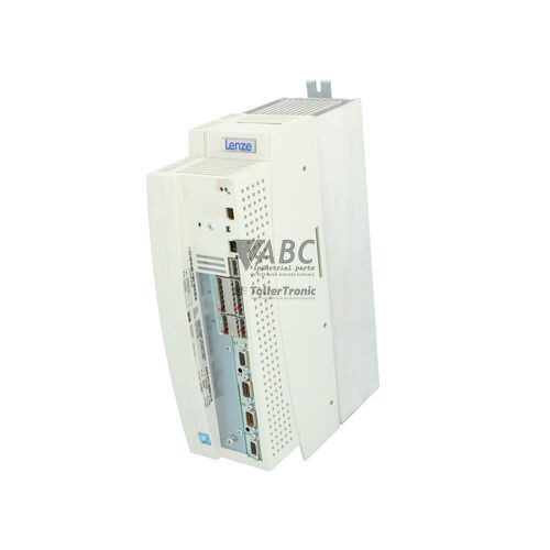
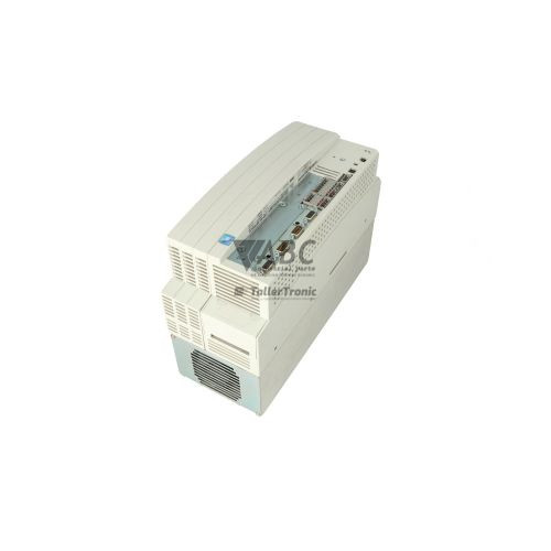
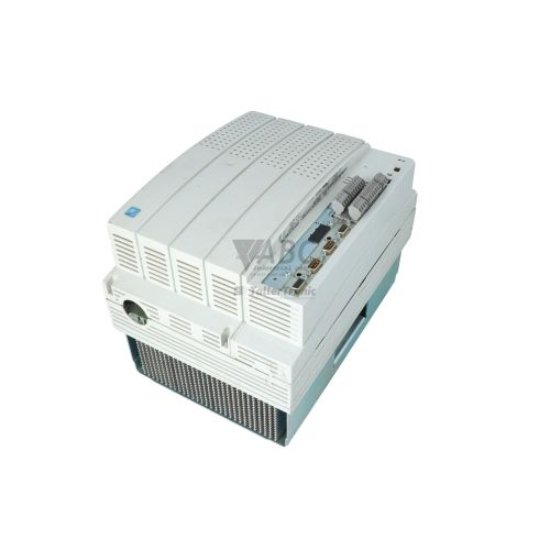
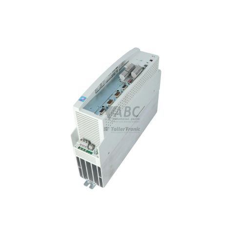
Lenze 13431038 EVS9326-ES 11 kW 9300 Servo Drive


Het item werd toegevoegd aan uw offerteaanvraag
Product Information
The Lenze 13431038 EVS9326-ES is an 11 kW stand-alone servo drive from the 9300 Servo family, engineered for high-dynamic motion control applications such as packaging machines, automated material handling, and multi-axis gantry positioning systems. Powered by a three-phase mains supply spanning 320 V AC to 528 V AC with a nominal input current of 20 A, this servo inverter delivers a continuous output current of 23.5 A and a maximum short-term peak current of 35.3 A for up to 60 seconds. Running at an internal switching frequency of 8 kHz and a maximum output frequency of 480 Hz, the unit provides precise motor torque and speed regulation across demanding production environments.
For closed-loop feedback, the drive is equipped with dedicated Sub-D terminal inputs accepting resolver or incremental encoder signals. System integration is facilitated through an integrated ISO 11898-compliant CANbus system bus operating at up to 500 kbit/s via screw terminals, alongside a front-facing Automation Interface (AIF) slot. This modular slot accommodates plug-in fieldbus adapters, including the EMF2133IB PROFIBUS-DP module, EMF2111IB INTERBUS module, or EMF2102IB LECOM RS232/RS485 adapters. Commissioning or replacing an existing drive requires transferring parameter data, which is stored in internal non-volatile EEPROM supporting up to four independent parameter sets. Parameters can be extracted and cloned directly using the pluggable EMZ9371BC keypad module or loaded via Global Drive Control (GDC) software, with assistance available through ABC Industrial Parts when extracting parameters from donor units or backed-up files.
Diagnostic information is provided through three front-panel status LEDs—Ready, IMP, and Trip—as well as the EMZ9371BC keypad display, GDC software diagnostic windows, a digital TRIP output signal, and an internal fault history buffer recorded under parameter code C0168. The drive actively monitors operational conditions, generating explicit fault codes such as OC1 for output short circuits, OU for DC bus overvoltage, LU for undervoltage, and LP1 for incoming mains phase failures. First-line troubleshooting involves measuring the three-phase AC input supply, verifying encoder cable connections, and checking brake resistor connections or fieldbus module seating in the AIF slot. When internal logic or power stage hardware errors like H05 or unrecoverable EEPROM corruption occur, field repairs are not feasible, and replacing the drive or sending it for bench repair through ABC Industrial Parts offers the quickest path back to full production.
Technical Specifications
| Manufacturer | Lenze |
| Part Number | 13431038 |
| Model / Type | EVS9326-ES |
| Component Type | Servo Drive |
| Product Family | 9300 Servo |
| Rated Power Output | 11 kW |
| Supply Voltage Range | 320 V AC to 528 V AC |
| Nominal Mains Input Current | 20 A |
| Continuous Output Current | 23.5 A |
| Peak Output Current (60s) | 35.3 A |
| Switching Frequency | 8 kHz |
| Maximum Output Frequency | 480 Hz |
| System Bus Interface | CANbus (ISO 11898, up to 500 kbit/s) |
| Automation Interface Options | PROFIBUS-DP (EMF2133IB), INTERBUS (EMF2111IB), LECOM RS232/RS485 (EMF2102IB) |
| Motor Feedback Connections | Sub-D terminals for Resolver / Incremental Encoder |
| Parameter Storage | Non-volatile EEPROM (Up to 4 Parameter Sets) |
Programming and Configuration
Configuring and commissioning the Lenze EVS9326-ES relies on Lenze Global Drive Control (GDC) software or the optional pluggable EMZ9371BC keypad module. The drive features non-volatile internal EEPROM memory capable of storing up to four distinct, full parameter sets. This multi-dataset capability allows users to store backup configurations or switch between distinct operating profiles without needing constant external reprogramming.
For rapid replacement during routine maintenance, parameters can be cloned directly into the memory of the EMZ9371BC keypad module and written to a replacement drive without connecting a PC. When using GDC software, technicians can back up, edit, and upload complete parameter files over the communication interface. Proper alignment of parameter sets is required before placing a unit into service to ensure correct motor feedback, control loops, and speed limits match the application requirements.
Communication and System Integration
The EVS9326-ES servo drive features built-in system bus connectivity via an integrated CANbus interface compliant with ISO 11898. Terminated via screw terminals, this CANbus connection supports communication speeds up to 500 kbit/s, enabling high-speed real-time process data exchange between multiple drives or higher-level controllers.
Network expansion is accomplished using the front-side Automation Interface (AIF) slot. The drive supports a selection of modular fieldbus adapters, including the EMF2133IB for PROFIBUS-DP, the EMF2111IB for INTERBUS, and the EMF2102IB for LECOM RS232/RS485 serial communication. Motor feedback is routed directly to dedicated Sub-D connectors, supporting both standard resolvers and incremental encoders for closed-loop motion regulation.
Diagnostics and Status Indication
System diagnostics on the Lenze EVS9326-ES are monitored through both hardware visual indicators and software monitoring windows. The drive features three primary status LEDs on its panel: a green Ready LED indicating normal operational readiness, a yellow IMP LED signaling that pulse inhibit is active and power output is disabled, and a red Trip LED that flashes to signal an active drive fault.
Advanced diagnostic feedback is accessed via the EMZ9371BC keypad display or the diagnostic monitoring window within Global Drive Control (GDC) software. Fault events are automatically logged into a persistent fault history buffer under parameter code C0168, while a dedicated digital output provides a hardwired TRIP signal to master machine controllers.
Status LED Indicators
| LED | Color/Status | Meaning |
|---|---|---|
| Ready | Green - Solid | Operational status indicator; solid ON indicates drive is ready for operation. |
| IMP | Yellow - Solid | Pulse inhibit active; power stage output is disabled. |
| Trip | Red - Flashing | Drive fault state active (TRIP condition). Flashing pattern indicates general fault category. |
Replacement and Spare Part Considerations
When swapping a failed Lenze EVS9326-ES servo drive with a replacement unit, exact matching of the part number 13431038 and model specification ensures identical electrical ratings, including the 11 kW power output, 23.5 A continuous current, and 35.3 A peak capacity. Fieldbus communication modules installed in the AIF slot, such as PROFIBUS (EMF2133IB) or INTERBUS (EMF2111IB), must be transferred from the original unit to the replacement drive to maintain network compatibility.
A replacement unit is not plug-and-run out of the box and requires parameter configuration before power stage activation. Parameter datasets must be uploaded via GDC software or restored using the cloned memory of an EMZ9371BC keypad module. Prior to running the motor, verify that input line power across terminals L1, L2, and L3 is balanced and that resolver/encoder Sub-D feedback connections are securely fastened to avoid instant TRIP conditions.
Error Codes & Fault Codes
The following error codes may be displayed during operation or diagnostics:
| Code | Name | Description | Possible Cause | Recommended Action |
|---|---|---|---|---|
| OC1 | Short Circuit | Short circuit at motor terminals or power stage failure. | Short circuit in motor cable, motor winding fault, or drive output stage failure. | Check motor and output wiring for short circuits or earth faults; test motor insulation. If error persists with motor disconnected, internal hardware fault requires return for repair. |
| OC2 | Earth Fault | Earth ground fault at drive output. | Ground fault in motor lead or motor winding, excessive capacitive ground leakage current. | Check motor cable and motor for insulation ground faults. |
| OC5 | I x t Overload | Continuous overload threshold reached (Ixt overload). | Drive operated above rated output current for too long, mechanical overload or stall. | Check mechanical load, motor sizing, and acceleration/deceleration profiles. |
| OU | Overvoltage DC Bus | DC bus voltage threshold exceeded. | Excessive regenerative energy during deceleration, brake chopper inactive or braking resistor open/faulty. | Extend deceleration time, inspect external brake resistor and internal brake transistor. |
| LU | Undervoltage DC Bus | DC bus voltage dropped below minimum threshold. | Mains supply power interruption, supply phase missing, main contactor dropped out. | Verify input supply voltage and line fuses. |
| OH | Heatsink Overtemperature | Heatsink temperature exceeded upper limit. | Insufficient cooling, fan failure, ambient temperature too high, dirty heatsink fins. | Clean heatsink, verify cabinet ventilation and cabinet internal cooling fans. |
| OH4 | Motor Overtemperature | Motor temperature sensor (PTC / Klixon) triggered overtemperature. | Motor thermal overload, cooling fan failure on motor, broken sensor wire. | Allow motor to cool, verify motor loading and temperature sensor connections. |
| OH7 | Motor Temp Sensor Open / Short | Motor temperature sensor monitoring circuit detected open circuit or short circuit. | Disconnected temperature sensor wire or faulty sensor. | Inspect connections on control terminals T1/T2. |
| NMAX | Overspeed | Motor speed exceeded maximum permissible speed limit. | Incorrect speed controller tuning, encoder feedback noise/failure, overhauling load. | Verify encoder feedback connection, check maximum speed parameter limits and tuning. |
| CE0 | AIF Communication Fault | Communication failure on Automation Interface module. | Fieldbus master fault, loose module connection, cabling defect. | Check module seating in slot AIF, check fieldbus cable and master state. |
| CE1 | CAN In1 Time-Out | Time-out error on CAN object CAN-IN1. | System bus interruption, CAN master stopped sending process data. | Verify CANbus wiring, termination resistors, and transmitter node. |
| EER | EEPROM Fault | Internal EEPROM checksum error during power-up or parameter write. | Corrupted non-volatile memory or failed EEPROM chip. | Attempt factory reset parameter load; if error persists, internal hardware fault requires unit repair or replacement. |
| H05 | Internal Hardware Error | Internal control board monitoring error. | Failure on internal control board logic. | Internal hardware fault — return unit for service or repair. |
| LP1 | Mains Phase Failure | One phase of the 3-phase AC power input is missing. | Blown line fuse, loose input power terminal connection, unstable main supply. | Check AC supply voltage across all three incoming phases (L1, L2, L3). |
Frequently Asked Questions
What software is used to program and configure the Lenze EVS9326-ES?
Lenze Global Drive Control (GDC) software is used to program, monitor, and configure the EVS9326-ES drive. Parameters can also be adjusted or cloned using the pluggable EMZ9371BC keypad module.
Can parameter settings be transferred without connecting a laptop?
Yes, parameter settings can be copied directly to the memory of an EMZ9371BC keypad module from the original drive and cloned onto the replacement unit without using a computer.
What causes an LP1 fault code on the EVS9326-ES servo drive?
An LP1 fault code indicates a mains phase failure where one phase of the incoming 3-phase AC power input is missing. This can be caused by a blown line fuse, loose power terminal wiring, or an unstable main power supply.
What communication interfaces are integrated into the Lenze 13431038 drive?
The drive includes an integrated ISO 11898 CANbus system bus running up to 500 kbit/s via screw terminals, as well as an Automation Interface (AIF) slot that supports optional fieldbus modules such as PROFIBUS-DP (EMF2133IB), INTERBUS (EMF2111IB), and LECOM RS232/RS485 adapters (EMF2102IB).
What should be done if the drive displays fault code H05 or EER?
Fault code H05 indicates an internal control board monitoring hardware error, while EER indicates internal EEPROM corruption. If an EER error persists after attempting a factory reset parameter reload, both conditions point to internal hardware failures that require sending the drive for repair or replacing the unit.
Take advantage of our exchange formula
A defective product does not have to be worthless. At ABC Industrial Parts, you can hand in defective products and immediately benefit from a discount on your new purchase. This is a smart way to save money while contributing to a circular economy.
Play it safe with our warranty conditions
Industrial plants prefer to keep running invariably, no matter what. Therefore, it is essential that you can rely on high-quality products and/or sustainable repairs. With our warranty conditions, you can count on certainty, whether you choose new, used or repaired products.
Data backup and recovery
Have you lost valuable parameters or data due to a malfunction while the manufacturer no longer provides support? At ABC Industrial Parts, we help you secure this data, both for common and specific products.
Specific firmware and hardware versions
If you are working with specific hardware or firmware versions that are no longer available from the manufacturer, ABC Industrial Parts is your partner. When making your enquiry, clearly state which versions you need, we will then look at the possibilities of supplying those versions, so that your installations continue to function optimally.
Disclaimer:
We are not an authorised distributor of Lenze.
Product photos are for illustration purposes only and may differ from the actual product delivered.
Some of the content on this page was created with the help of AI. While we strive to provide accurate and up-to-date information, errors may occur.