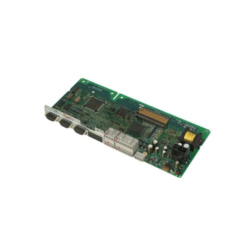
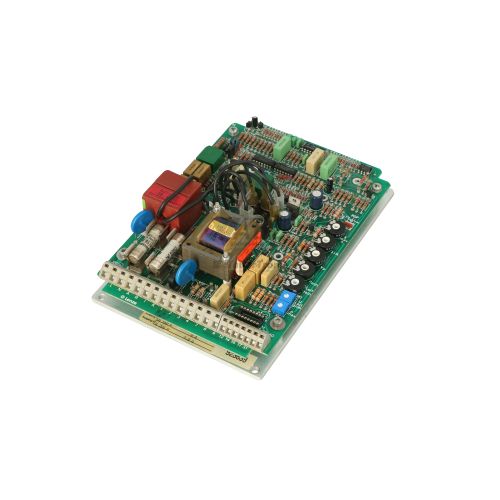
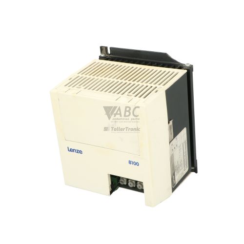
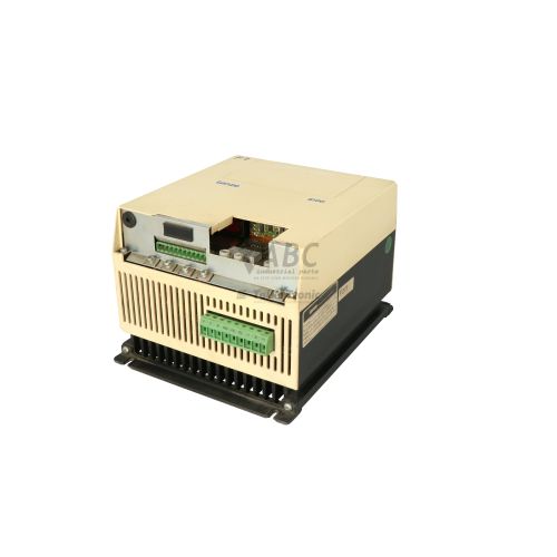
Lenze 9325MP.2G.81 Power Board – 9300 Series 11 kW Power Stage Module


Het item werd toegevoegd aan uw offerteaanvraag
Product Information
The Lenze 9325MP.2G.81 is an internal power board designed as the core power stage module for 11 kW drives in the Lenze 9300 Series. Built specifically for frame size 9325 devices such as the EVS9325-EV frequency inverter and EVF9325-EV servo drive, this power module performs high-efficiency power conversion using a heavy-duty IGBT architecture. It operates across a 3-phase mains supply voltage range of 320 V AC to 528 V AC at 45 to 65 Hz, providing a continuous rated output current of 23.5 A and a peak current capability of 35.3 A for up to 60 seconds. Rated for a thermal power loss dissipation of 320 W, the assembly delivers reliable power handling in demanding motion control and industrial driving applications.
Connecting the unit to the drive infrastructure involves dedicated (+UG, -UG) DC bus screw terminals for high-voltage DC distribution alongside a multi-pin connector interface that joins the power chassis directly to the detachable front control card. Because parameters, program files, and runtime settings are retained on the existing plug-in control card, replacing a damaged power board with a functional spare requires no software reprogramming or parameter downloads. Commissioning a replacement unit requires standard hand tools, proper electrostatic discharge protection, and applying a thin, even layer of fresh thermal compound across the heatsink interface to ensure effective heat transfer. Maintenance teams sourcing a spare module through ABC Industrial Parts can complete board-level hardware replacement quickly to restore functional drive operation without altering existing application configurations.
Diagnostic status is communicated directly on the drive via front status LEDs, including a solid Green LED (READY) indicating normal power stage operation, a solid Yellow LED (IMP) indicating active pulse inhibit via terminal control, and a solid Red LED (TRIP / FAIL) signifying an active fault state with disabled inverter pulses. Detailed fault logs and operational metrics are accessible through the Lenze 9371BB XT Keypad or via Global Drive Control (GDC) diagnostic software. Diagnostic indications highlight issues such as DC bus overvoltage (OU), DC bus undervoltage (LU), short circuits (OC1), or heatsink overtemperature (OH). When facing unrecoverable internal hardware errors or gate driver failures such as error H05, board-level repairs or acquiring a tested exchange board from ABC Industrial Parts offers a dependable path to minimizing plant downtime.
Technical Specifications
| Manufacturer | Lenze |
| Part Number | 9325MP.2G.81 |
| Model / Type | Power Board |
| Component Type | Power Stage Module |
| Product Family | 9300 Series |
| Compatible Frame Size | Frame Size 9325 (11 kW) |
| Compatible Drives | EVS9325-EV, EVF9325-EV |
| Rated Power | 11 kW |
| Supply Voltage Range | 320 - 528 V AC |
| Mains Frequency | 45 - 65 Hz |
| Rated Output Current | 23.5 A |
| Peak Output Current | 35.3 A |
| Power Loss | 320 W |
Programming and Configuration
The Lenze 9325MP.2G.81 power board functions as the hardware power stage within the modular 9300 Series drive architecture. Because control intelligence and user parameter configurations reside entirely on the detachable front control card, the power board itself contains no non-volatile parameter memory. When replacing a damaged 9325MP.2G.81 power module, technicians simply transfer the original control card onto the new power chassis, ensuring all drive settings, motor data, and fieldbus node parameters remain completely intact.
For system diagnostics, parameter monitoring, or fine-tuning drive performance, engineers can connect to the drive using the Lenze 9371BB XT Keypad or the Global Drive Control (GDC) software tool. The GDC software allows comprehensive readouts of internal status flags, error history logs, and actual operational parameters. Because the power stage hardware directly mirrors factory specifications, no parameter calibration, firmware updating, or software download is necessary following a board replacement.
Communication and System Integration
System integration for the 9325MP.2G.81 power board centers on robust electrical connections designed for high-power industrial environments. The board is equipped with dedicated high-current screw terminals for (+UG, -UG) DC bus link interconnections, allowing shared DC bus configurations or connection to external braking components. Power output terminals interface directly with the motor, supporting continuous operating currents up to 23.5 A and transient overload currents up to 35.3 A.
Control signals and switching commands pass between the host power chassis and the plug-in control card through an integrated multi-pin header interface. This interface routes gate drive control signals, current feedback measurement signals, and thermal sensor feedback to the control module. The board is fully compatible with Lenze EVS9325-EV vector inverters and EVF9325-EV servo drives operating in automotive manufacturing, material handling, conveyor systems, packaging machinery, and textile processing lines.
Diagnostics and Status Indication
The drive assembly provides immediate visual feedback via three status LEDs on the front panel. A solid Green LED (READY) indicates that both control power and the power stage are operating normally and ready for run commands. A solid Yellow LED (IMP) shows that pulse inhibit is active, disabling inverter output via terminal input. A solid Red LED (TRIP / FAIL) signals an active fault condition where inverter pulses are blocked to protect the power stage from conditions such as overcurrent, overvoltage, or thermal overload.
For thorough troubleshooting, engineers can read error memory and fault diagnostic codes using the Lenze 9371BB XT Keypad or Global Drive Control (GDC) software. Additional hardware checks include verifying the DC bus voltage LED indicator and checking input voltage across the mains supply terminals.
Status LED Indicators
| LED | Color/Status | Meaning |
|---|---|---|
| Red LED (TRIP / FAIL) | Red - Solid | Fault state active; inverter pulses disabled. May indicate overcurrent, overvoltage, power stage thermal overload, or internal board failure. |
| Green LED (READY) | Green - Solid | Inverter power stage and control power normal; ready for operation. |
| Yellow LED (IMP) | Yellow - Solid | Pulse inhibit active / drive disabled via terminal input. |
Replacement and Spare Part Considerations
When replacing an internal power board on a Lenze 9300 series 11 kW drive, maintaining exact hardware compatibility is essential. The 9325MP.2G.81 module is designed specifically for frame size 9325 drives, such as the EVS9325-EV frequency inverter and EVF9325-EV servo drive. Technicians should verify that the replacement power board matches the 11 kW power rating and 23.5 A output current specifications to prevent drive trips or thermal overload conditions.
During installation, mechanical and thermal preparation must be performed carefully. Proper electrostatic discharge (ESD) precautions should be observed when handling circuit boards. Existing thermal paste on the drive heatsink must be thoroughly cleaned off and replaced with a fresh layer of thermal compound before mounting the 9325MP.2G.81. This step prevents localized thermal hotspots and ensures heat from the IGBT power stage dissipates efficiently into the heatsink.
Because drive parameters reside on the detachable front control module, swapping the power board does not require re-entering parameters or re-flashing software. After transferring the existing control card onto the replacement power board chassis and securing all (+UG, -UG) DC bus and terminal connections, power can be safely re-applied to test drive operation.
Error Codes & Fault Codes
The following error codes may be displayed during operation or diagnostics:
| Code | Name | Description | Possible Cause | Recommended Action |
|---|---|---|---|---|
| OC1 | Short Circuit / Earth Fault | Instantaneous power stage overcurrent threshold exceeded. | Motor winding short circuit, short to earth/ground, defective IGBT power stage, or damaged gate driver circuit on power board. | Check motor and motor cable insulation. Disconnect motor and re-test drive. If fault persists with motor disconnected, return power board for repair/replacement. |
| OC2 | Acceleration Overcurrent | Excessive motor current detected during acceleration ramp. | Acceleration time too short, mechanical overload, or current measurement calibration fault on power board. | Extend acceleration time, check motor load, or inspect power board current sensing shunts/sensors. |
| OC5 | I2t Overload | Drive continuous overload limit reached (overcurrent for extended time). | Drive undersized for load duty cycle or continuous mechanical jamming. | Reduce motor load, verify duty cycle, or check cooling fan airflow on power stage. |
| OU | DC-Bus Overvoltage | DC bus voltage exceeded upper cutoff threshold (> 770 V DC). | Braking energy feedback from motor during deceleration, brake chopper resistor open/faulty, or mains overvoltage. | Extend deceleration time, verify brake resistor connection and braking transistor activation on power board. |
| LU | DC-Bus Undervoltage | DC bus voltage dropped below minimum threshold (< 430 V DC). | Mains supply loss, blown mains fuse, or defective pre-charge circuit on power board. | Check mains voltage and supply line fuses. If line voltage is present but DC bus stays low, inspect pre-charge relay and resistors on power board. |
| OH | Heatsink Overtemperature | Power board IGBT heatsink temperature exceeds maximum threshold (> 85°C / 90°C). | Inadequate cooling, clogged heatsink fins, failed heatsink fan, or dried/missing thermal paste between power module and heatsink. | Clean heatsink, replace cooling fan, check ambient temperature, and verify thermal compound layer. |
| OH4 | Drive Thermal Overload | Calculated power stage thermal load threshold reached. | High ambient temperature combined with high continuous switching frequency. | Reduce carrier/switching frequency or improve cabinet ventilation. |
| LP1 | Mains Phase Loss | Phase unbalance or loss of single mains supply phase detected. | One input phase missing or line supply imbalance exceeding limit. | Check input supply lines and line fuses under load conditions. |
| H05 | Internal Hardware Fault | Power stage driver error or internal power board self-test failure. | Hardware error on gate driver circuit, defective power board supply, or corrupted feedback signal. | Internal board failure — replace power board assembly (9325MP.2G.81) or return complete unit for service. |
Frequently Asked Questions
Does replacing the Lenze 9325MP.2G.81 power board require parameter re-programming?
No, parameter re-programming is not required. User drive parameters, motor settings, and network configurations are stored on the original detachable control card, which is transferred directly onto the replacement power board assembly.
Which drive models are compatible with the 9325MP.2G.81 power stage board?
The 9325MP.2G.81 power board is compatible with Lenze 9300 Series frame size 9325 (11 kW) drives, including the EVS9325-EV frequency inverter and EVF9325-EV servo drive.
What critical steps are required when installing a replacement power board?
Installation requires proper ESD protection, thorough cleaning of the heatsink surface, applying fresh thermal compound between the IGBT module and heatsink, and securely tightening the (+UG, -UG) DC bus screw terminals and multi-pin control connectors.
What does a solid Red LED indicate on a drive with the 9325MP.2G.81 power board?
A solid Red LED (TRIP / FAIL) indicates an active fault state with inverter pulses disabled. This can be caused by conditions such as overcurrent, DC bus overvoltage, thermal overload, or an internal hardware failure like fault H05.
How can error history and diagnostics be read from the drive?
Error history and operational status can be inspected using the plug-in Lenze 9371BB XT Keypad display or by connecting PC software via Lenze Global Drive Control (GDC).
Take advantage of our exchange formula
A defective product does not have to be worthless. At ABC Industrial Parts, you can hand in defective products and immediately benefit from a discount on your new purchase. This is a smart way to save money while contributing to a circular economy.
Play it safe with our warranty conditions
Industrial plants prefer to keep running invariably, no matter what. Therefore, it is essential that you can rely on high-quality products and/or sustainable repairs. With our warranty conditions, you can count on certainty, whether you choose new, used or repaired products.
Data backup and recovery
Have you lost valuable parameters or data due to a malfunction while the manufacturer no longer provides support? At ABC Industrial Parts, we help you secure this data, both for common and specific products.
Specific firmware and hardware versions
If you are working with specific hardware or firmware versions that are no longer available from the manufacturer, ABC Industrial Parts is your partner. When making your enquiry, clearly state which versions you need, we will then look at the possibilities of supplying those versions, so that your installations continue to function optimally.
Disclaimer:
We are not an authorised distributor of Lenze.
Product photos are for illustration purposes only and may differ from the actual product delivered.
Some of the content on this page was created with the help of AI. While we strive to provide accurate and up-to-date information, errors may occur.