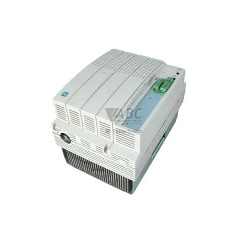
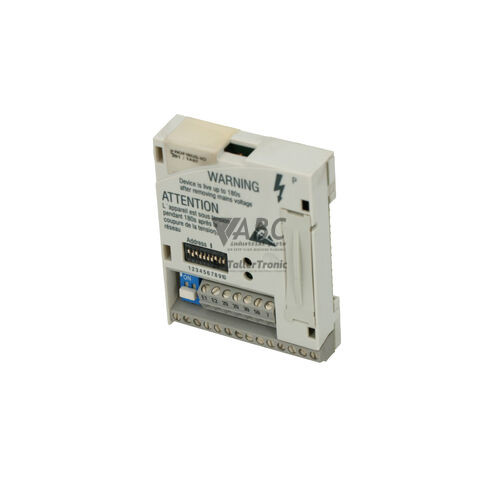
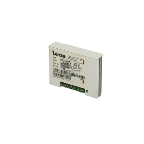
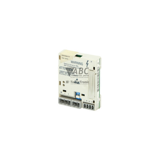
Lenze 13013069 E82ZAFVC010 Standard I/O Function Module


Het item werd toegevoegd aan uw offerteaanvraag
Product Information
The Lenze 13013069, model E82ZAFVC010, is a standard I/O function module designed for the Lenze 8200 vector frequency inverter family. Mounted directly into the inverter Front Interface (FIF) slot, this compact module provides essential digital and analog control expansion for general machine automation, including packaging machinery, conveyor systems, and textile manufacturing. Physical features include pluggable screw terminal connectors and integrated auxiliary power sources—a 10 V DC output for setpoint potentiometers and a 20 V DC output for auxiliary control circuits. The module incorporates four HTL digital inputs operating between 12 V DC and 30 V DC for HIGH signals, one open-collector digital output rated at 24 V DC at 50 mA, one 10-bit resolution analog input, and one configurable analog output.
Connecting the E82ZAFVC010 to a host inverter is handled through the direct snap-in Front Interface (FIF) slot and pluggable screw terminals that permit field maintenance without disconnecting individual control wires. Hardware replacement is straightforward because all operational drive parameters reside within the host Lenze 8200 vector inverter EEPROM rather than on the function module itself, eliminating the need to perform parameter transfers or software re-commissioning when installing a replacement board. For setup adjustments, signal monitoring, or parameter management, field technicians can utilize the EMF2171IB or E82ZBC Keypad XT module, or connect via Global Drive Control (GDC) software. When servicing existing production lines, sourcing a tested replacement through ABC Industrial Parts ensures direct compatibility with established drive configurations.
Diagnostic feedback is provided on the front panel via a dual-color red and green STATUS LED that indicates the operational state and fault conditions of the host inverter. In addition to the visual LED indicator, system status and diagnostic registers can be monitored through GDC software or displayed on an attached Keypad XT module. Common diagnostic fault codes include CE1 for communication interruptions at the FIF slot, CE0 for process data errors, EE0 for internal memory faults, OC1 for motor overcurrent conditions, and OU or LU for DC bus voltage anomalies. First-line troubleshooting should verify proper module seating in the FIF slot, terminal wiring integrity, and signal levels on input lines. If communication errors persist or internal drive hardware faults occur, replacing the module or sending the unit to ABC Industrial Parts for professional evaluation and repair will help minimize machine downtime.
Technical Specifications
| Manufacturer | Lenze |
| Part Number | 13013069 |
| Model / Type | E82ZAFVC010 |
| Product Family | 8200 vector |
| Component Type | Standard I/O Function Module |
| Mounting Type | Plug-in Front Interface (FIF) slot |
| Digital Inputs | 4 |
| Digital Input Level | HTL (LOW 0...3 V DC, HIGH 12...30 V DC) |
| Digital Outputs | 1 |
| Digital Output Rating | 24 V DC / 50 mA (Open Collector) |
| Analog Inputs | 1 (10-bit resolution) |
| Analog Input Signal Ranges | 0...10 V, 0...20 mA, 4...20 mA |
| Analog Outputs | 1 |
| Analog Output Signal Ranges | 0...10 V (max. 2 mA) or 0...20 mA |
| Reference Supply Output | 10 V DC (max. 10 mA) |
| Auxiliary Supply Output | 20 V DC (max. 20 mA) |
Programming and Configuration
The Lenze E82ZAFVC010 function module operates without storing independent program code or drive parameter sets on the board itself. All configuration data, setpoint scales, and I/O assignments are retained directly in the non-volatile EEPROM memory of the host Lenze 8200 vector frequency inverter. This centralized architecture ensures that replacing a damaged or failed module requires zero parameter transfer, as the newly installed module immediately adopts the stored configuration of the host drive upon power-up.
System configuration and parameter adjustments can be performed using Lenze Global Drive Control (GDC) software connected to the host drive. Alternatively, field adjustments such as modifying digital input functionality, setting up multi-preset speeds, or recalibrating analog setpoint scaling can be carried out using the EMF2171IB or E82ZBC Keypad XT operator panel attached to the inverter interface.
Communication and System Integration
Physical integration of the E82ZAFVC010 standard I/O module occurs via direct mechanical and electrical connection into the Front Interface (FIF) slot of the Lenze 8200 vector drive. External control wiring connects through pluggable screw terminal blocks, allowing rapid installation and removal. The module supports flexible analog input signals including 0 to 10 V, 0 to 20 mA, and 4 to 20 mA at 10-bit resolution, as well as an analog output configurable for 0 to 10 V (maximum 2 mA) or 0 to 20 mA for speed and load status feedback to external controllers.
Digital control interfacing consists of four HTL digital inputs with switching thresholds defined at LOW (0 to 3 V DC) and HIGH (12 to 30 V DC), suitable for machine start, stop, direction, and multi-preset speed switching. A single 24 V DC open-collector digital output capable of sinking or sourcing 50 mA provides run or fault indication to external PLC systems or control relays. Onboard power outputs supply 10 V DC at up to 10 mA for direct potentiometer reference and 20 V DC at up to 20 mA for sensor and auxiliary input powering.
Diagnostics and Status Indication
The E82ZAFVC010 provides clear operational feedback through a multi-color front panel STATUS LED. The LED displays solid and flashing red or green illumination states to communicate normal drive operation, pending warnings, or active fault conditions on the host frequency inverter.
For deeper diagnostic analysis, maintenance personnel can review diagnostic monitoring registers through Global Drive Control (GDC) software or read diagnostic codes directly from the EMF2171IB / E82ZBC Keypad XT panel when attached to the drive.
Status LED Indicators
| LED | Color/Status | Meaning |
|---|---|---|
| STATUS | Red/Green - Solid / Flashing | Indicates operational state and fault conditions of the host drive |
Replacement and Spare Part Considerations
Replacing a Lenze 13013069 E82ZAFVC010 standard I/O module is a straightforward maintenance procedure due to its plug-and-play design. Because parameter data is maintained entirely in the EEPROM memory of the host 8200 vector frequency inverter, no software upload, parameter copy, or re-commissioning sequence is required when fitting a spare module.
During replacement, ensure the drive is fully powered down before unplugging the control terminal blocks and removing the module from the Front Interface (FIF) slot. When installing the replacement unit, verify that the module is firmly seated in the slot and that all pluggable screw terminals are securely fastened to maintain reliable signal integrity.
Error Codes & Fault Codes
The following error codes may be displayed during operation or diagnostics:
| Code | Name | Description | Possible Cause | Recommended Action |
|---|---|---|---|---|
| CE1 | Communication error at FIF slot | Communication failure or interruption between host inverter and function module plugged into Front Interface slot. | Function module loose or improperly seated in FIF slot; defective module or internal communication hardware failure. | Check module seating in FIF slot; verify terminal connections; power cycle unit; if problem persists, return unit/module for repair. |
| CE0 | Communication error process data | Interruption in process data transmission via function module interface. | External signal loss or interferences on signal lines. | Check control wiring and signal levels on input terminals. |
| EE0 | EEPROM memory error | Internal non-volatile memory error on host drive. | EEPROM corrupted or internal hardware fault. | Internal hardware fault — reload default parameters or return unit for repair. |
| OC1 | Short circuit / Overcurrent | Instantaneous overcurrent condition detected on motor outputs. | Short circuit in motor cable or motor winding; excessive acceleration rate. | Check motor and cable insulation; check acceleration time configuration. |
| OU | Overvoltage DC bus | DC bus voltage exceeded upper limit threshold. | Excessive motor deceleration energy / generator mode without braking resistor. | Increase deceleration time or connect braking module/resistor. |
| LU | Undervoltage DC bus | DC bus voltage fell below minimum allowable threshold. | Mains supply voltage drop, phase failure, or power supply interrupt. | Check line input voltage and power supply connection. |
| OH | Overtemperature inverter | Inverter heatsink temperature limit exceeded. | Insufficient cooling, fan failure, ambient temperature too high, excessive load. | Clean cooling fins, check fan operation, reduce ambient temperature. |
Frequently Asked Questions
Does replacing the Lenze E82ZAFVC010 module require parameter reprogramming?
No. All operational parameter data resides in the non-volatile EEPROM memory of the host Lenze 8200 vector frequency inverter, so no parameter programming is required when replacing the module.
What physical interface is used to connect the E82ZAFVC010 to the inverter?
The module plugs directly into the Front Interface (FIF) slot on the front of the Lenze 8200 vector frequency inverter and uses pluggable screw terminals for external I/O wiring.
What analog signal types does the E82ZAFVC010 support?
The analog input supports 0-10 V, 0-20 mA, and 4-20 mA ranges with 10-bit resolution. The analog output supports 0-10 V (maximum 2 mA) or 0-20 mA.
How does the module indicate drive status and fault conditions?
A dual-color Red/Green STATUS LED on the front panel displays solid or flashing states to indicate drive status and active fault conditions. Detailed diagnostic codes can also be accessed via Global Drive Control (GDC) software or an optional Keypad XT.
What does fault code CE1 signify on a Lenze 8200 vector drive?
Fault code CE1 indicates a communication error at the Front Interface (FIF) slot. It is typically caused by a loose or improperly seated module, terminal wiring issues, or an internal communication hardware failure.
Take advantage of our exchange formula
A defective product does not have to be worthless. At ABC Industrial Parts, you can hand in defective products and immediately benefit from a discount on your new purchase. This is a smart way to save money while contributing to a circular economy.
Play it safe with our warranty conditions
Industrial plants prefer to keep running invariably, no matter what. Therefore, it is essential that you can rely on high-quality products and/or sustainable repairs. With our warranty conditions, you can count on certainty, whether you choose new, used or repaired products.
Data backup and recovery
Have you lost valuable parameters or data due to a malfunction while the manufacturer no longer provides support? At ABC Industrial Parts, we help you secure this data, both for common and specific products.
Specific firmware and hardware versions
If you are working with specific hardware or firmware versions that are no longer available from the manufacturer, ABC Industrial Parts is your partner. When making your enquiry, clearly state which versions you need, we will then look at the possibilities of supplying those versions, so that your installations continue to function optimally.
Disclaimer:
We are not an authorised distributor of Lenze.
Product photos are for illustration purposes only and may differ from the actual product delivered.
Some of the content on this page was created with the help of AI. While we strive to provide accurate and up-to-date information, errors may occur.